
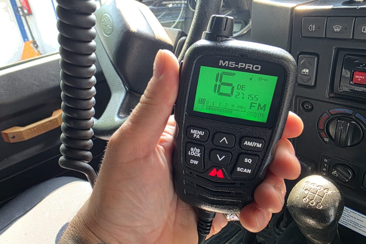

Why does an antenna produce signals when an alternating voltage is applied, and how is speech carried on that? Welcome to radio, or more precisely, CB radio. It still matters when it comes to travel and off-road driving. In this series we’ll walk you through the tech.
We’ve got a bit of a balancing act ahead of us here. Radio and signal technology is very complex, especially at high frequencies once you’re into the megahertz (MHz) and gigahertz (GHz) range. There’s a reason people in the trade say “HF is a bitch!” What they mean is that high-frequency alternating voltages throw up all sorts of effects that engineers have to keep in check. Suddenly the tracks on a circuit board turn into transmitters, power vanishes somewhere, and the signal doesn’t end up where it’s supposed to. Often no amount of calculation or prediction helps any more, only trial and error. And that’s exactly where radio and CB radio live, up in the high-frequency range.
To put it in context: CB radio is a radio system just like amateur radio. The differences are technical, down to the frequency ranges, the transmit power on offer and the requirements the operator has to meet. Amateur radio uses frequencies below and above the CB band, and the operator needs training that ends with a licence. CB stands for “Citizens’ Band Radio”. Open to everyone, but in return capped at 4 watts of transmit power. At 27 MHz (26.565 MHz to 27.405 MHz), CB radio sits in the high-frequency range.
That makes CB radio ideal for communication over short distances, something anyone can join in with straight away. All it takes is a set, a cable and an antenna, and you’re in. Well, almost. There are CB installations that work nicely and others that don’t. How to put together a good installation is what we’ll explain in this part and the ones that follow.
The basics of the radio signal
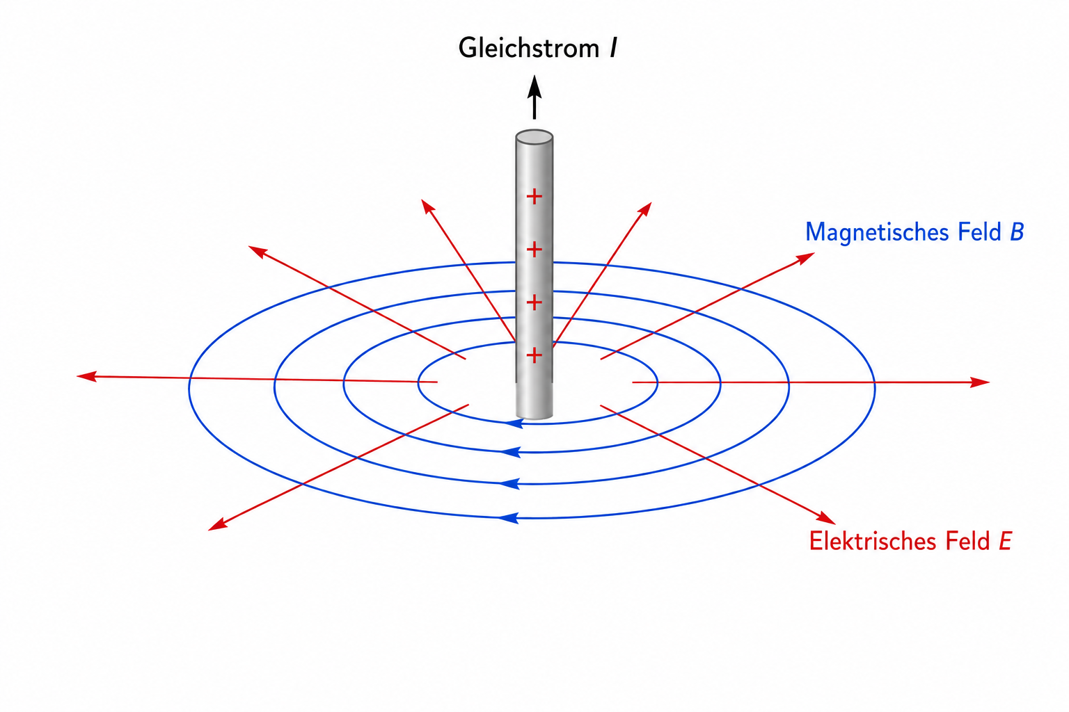
A radio signal is always an oscillation. You can’t generate and transmit a signal with direct voltage or direct current. Every current creates an electric field (E) and a magnetic field (B) around the conductor. With direct voltage, a voltage potential is set up, say 20 volts, and the electrons in the conductor flow steadily in one direction. The fields that form are static too, tied to their source (the current in the conductor). No signal is radiated.
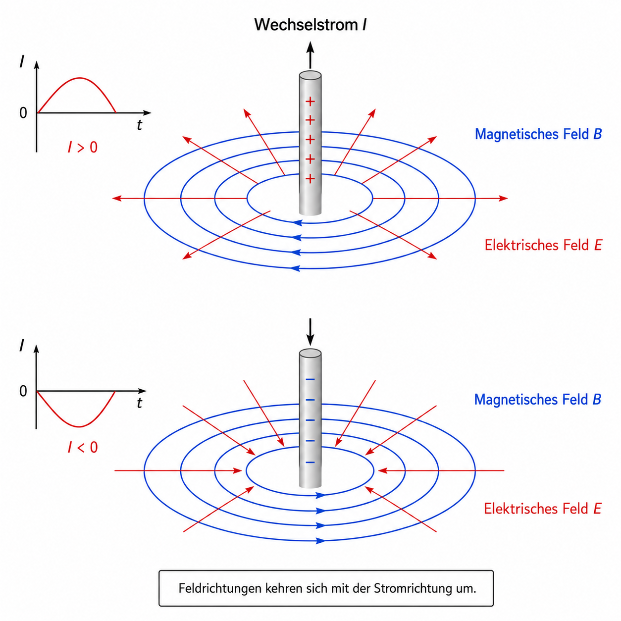
When the polarity flips periodically, plus and minus keep swapping over and the direction the current flows in reverses each time along with them. Then we’re talking about an alternating voltage, which results in an alternating current. We know this from the mains socket at home. There we have an alternating voltage that, at 50 hertz (Hz), swaps polarity 100 times a second.
In the process the electrons are constantly being accelerated and braked to extremes. Through those accelerations they build up and tear down an ever-changing electromagnetic field. And here’s where the crucial thing happens: the electric and magnetic fields are no longer static but change over time. They grow stronger and weaker again, offset from one another. The rule is:
- An electric field that changes over time creates a magnetic field.
- A magnetic field that changes over time creates an electric field.
That way they sustain each other and produce an electromagnetic wave that can break free of the conductor and be radiated.
Now you might think no power and no signal gets transmitted this way if the electrons only move back and forth. For that, just picture a Mexican wave in a stadium. People stand up, throw their arms in the air and sit back down. They haven’t moved anywhere, but the wave visibly runs across the stands. It’s the same thing here. The moment an electron is forced to change direction extremely fast, it gives off part of its energy as electromagnetic radiation (= standing up and throwing your hands in the air). And there’s our radio signal. The goal of the radio system is to carry this signal from the transmitter (the radio set) to the antenna with as little loss and interference as possible, so it can be radiated there.
With a radio signal the polarity changes happen far faster than with our mains supply at home. A CB set generates a signal at a frequency of around 27 MHz. As a result the polarity swaps 54,000,000 times a second.

Frequency and frequency band
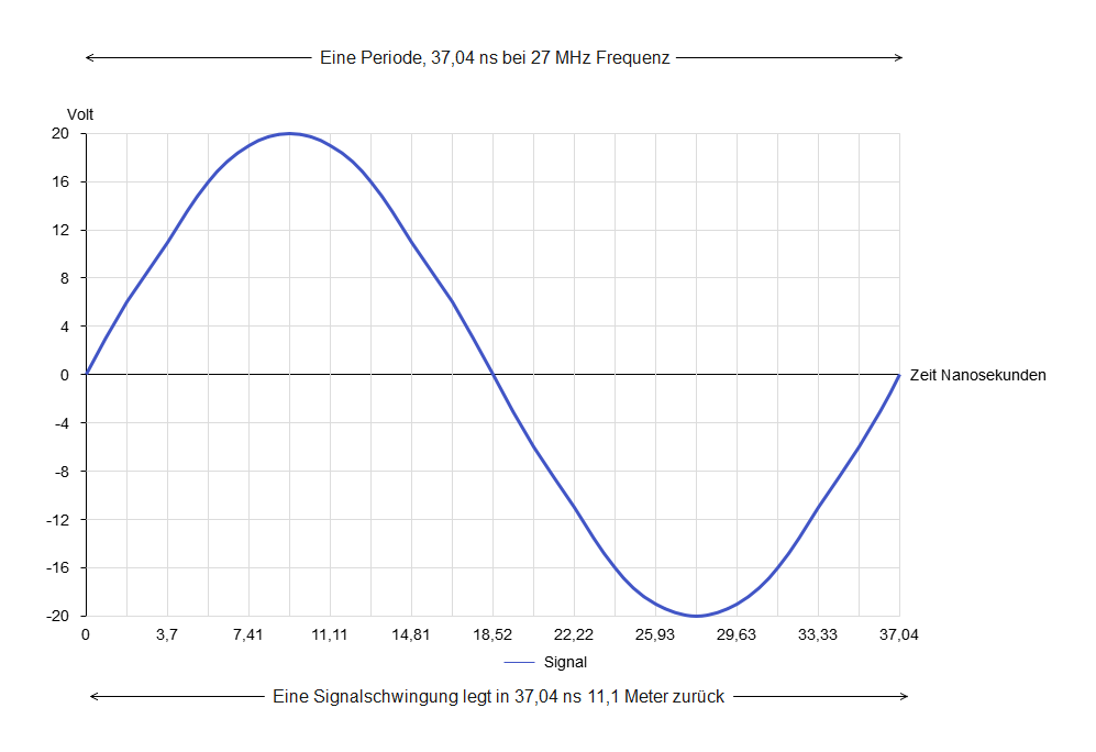
Maybe you’ve heard before that CB radio sits in the 11-metre band. So what does that mean again? It’s actually not that hard to grasp. CB radio uses a frequency of 27 MHz. That means the signal oscillates 27,000,000 times a second.
The radio signal produced this way travels through space at the speed of light (300,000 km/s). Put the two in relation to each other and the result is that one full cycle lasts 34.04 nanoseconds and covers 11.11 metres in that time. Those 11.11 metres are the wavelength lambda λ.
λ = c / f
11.11 m = 300,000 km/s / 27 MHz
AM and FM
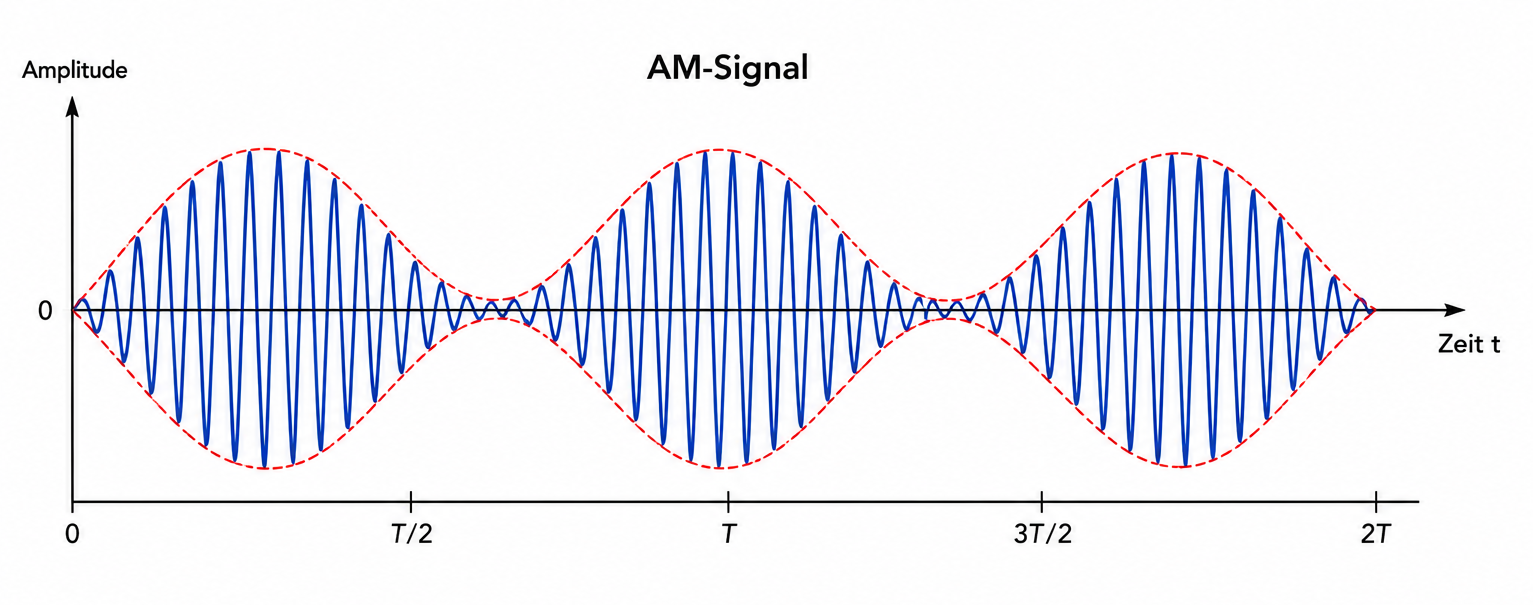
That leaves the question of how speech is carried on this wave. Here CB radio offers two methods: AM and FM. AM stands for amplitude modulation. When we speak into the microphone, we create positive and negative sound pressure. Following that sound pressure, the voltage (= the amplitude) is raised or lowered around a base voltage. On a 4 W CB set with 50 ohm impedance (more on that shortly), the base voltage is about 14.1 volts and the peak voltage about 20 volts, or -20 volts respectively.
For the receiver, though, the height of the amplitude doesn’t actually matter, but rather the change in the amplitude itself. In the receiving set, the incoming signal waves produce a current and a voltage again (a few microvolts). This is amplified so the amplitude changes become clear again. The receiver then reads the signal not from the actual height of the amplitude (the voltage) but from the rate of change of the amplitude over time. That’s where the speech information sits, which is then turned back into an audible signal. The envelope detector handles that job.
The downside with AM is that all sorts of electrical devices and systems inside or outside the car add false amplitudes to the radio signal, which distorts the speech signal. That could be the electronic ignition in the vehicle, a thunderstorm or large electrical installations in an industrial plant, for example. In other words, the signal is more prone to noise and crackle. Less common, but also possible, is individual amplitudes being weakened by different amounts due to features of the surroundings, which distorts the signal too.
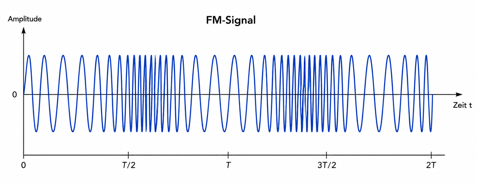
With FM it’s the frequency that gets changed. Starting from the base frequency of 27 MHz, it’s raised or lowered. The signal wave is squeezed or stretched, depending on the volume and pitch of what we speak into the mic. Here too the receiver reads the information from the difference to the base frequency. FM is less prone to noise, since the height of the amplitude doesn’t matter. The signal survives even when the signal strength (the amplitude) drops.
Impedance, or those mysterious 50 ohms
It’s important to understand impedance. It’s the deciding factor when it comes to transmit power and the standing wave ratio, SWR. Anyone who already knows their way around the term ohm or ohmic resistance still needs to take care here not to fall for a misunderstanding.
With direct current, conductors, cables and devices have an electrical resistance. They put up a resistance to the current flowing through them. An ordinary resistor, whose value is measured in ohms, sets the ratio of voltage to current. If you leave aside the moment a direct voltage is switched on and off, that ratio is fixed. The resistor reduces the current flow and turns the held-back energy into heat, work, light and so on. A load, a light bulb for instance, is also a kind of resistor that draws electrical power and produces light and heat.
With alternating voltage and current it behaves differently. Now the resistance no longer consists only of a part that hinders the current flow and draws energy. Instead there’s now a part that stores the energy temporarily and gives it back, and a part that slows down the changes in the current flow. Together these resistances are called impedance.
Without going into all these details here as well, this state of affairs has effects. Current and voltage can shift in time relative to each other. In engineering this is then referred to as capacitive and inductive reactances, which arise from the physical properties of the conductors, the antenna and so on.
Impedance depends on frequency. The higher the frequency, the stronger these effects become. At the 50 Hz of our mains grid they barely come into play, but in the high-frequency range they do. To create ideal conditions for the signal, all the components should have the same impedance. In other words, the reactances are equal in size and cancel each other out in their effect. That’s the target every operator wants to hit.
In CB radio, the components are matched to an impedance of 50 ohms at 27 MHz. Matching all the components to this value is important, because only then can the radio signal pass from one medium into the next without reflection (radio set > cable > antenna). Otherwise part of the signal, or rather the energy, gets reflected back. But the next two parts will deal with that in more detail.
Where do the 50 ohms come from?
When people were experimenting with the behaviour of cables and the like back in the 1930s, to work out how best to transmit high-frequency energy (radio signals included), the figure of 50 ohms came out of it. A compromise had to be found between the opposing demands of keeping power loss as low as possible and achieving the least attenuation. It turned out that the maximum power can be transmitted at 30 ohms impedance without the cable taking any damage. At 77 ohms, on the other hand, signals could be transmitted with the lowest attenuation loss. The compromise landed in the middle: 50 ohms.
Which raises the question of why TV and satellite reception ended up at 75 ohms? The reason is that the power is only transmitted over short distances there, so the power loss doesn’t matter. Here you can get closer to the ideal 77 ohms for the lowest attenuation.
How the radio system is built up
It all starts with the radio set, transmitter and receiver in one. It feeds the signal into the cable and picks the incoming signal back off it. Going by what we’ve learned so far, it’s clear that a plain cable won’t do the job here. It would already radiate the signal like an antenna and burn up the power. Remember, further up it said that alternating current creates electromagnetic fields around a conductor. And now comes an important point: the energy isn’t in the conductor, it’s in those fields. That’s why they have to be “locked in”. And that’s exactly what the coaxial cable does.
Coaxial cable
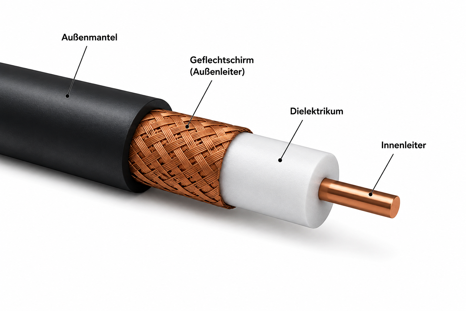
It’s connected to the radio set and makes the link to the antenna. The name coaxial cable comes from the way the cable is built: in the middle is the inner conductor, which is fed with the HF radio signal. It’s enclosed by an outer conductor mesh, which forms the counter-potential, the ground. Between them sits an insulating dielectric. The conductors run parallel along their axis, hence the name coaxial cable.
What is a dielectric?
The dielectric has three jobs:
- It insulates two conductors from each other.
- It fixes the conductors in their position.
- It influences the propagation speed of the electromagnetic field.
That makes the geometry formed by the two conductors and the dielectric, along with the material of the dielectric, the deciding factors for the coaxial cable’s impedance. The dielectric is usually made from plastics such as polyethylene (PE).
This construction creates a very important effect. The electric fields, where the energy sits, are trapped in the dielectric between the inner and outer conductor. A better picture would be a river guided by its banks but not stopped by them. The inner and outer conductor are the banks. The construction, and in particular the diameter of the dielectric, determines the impedance of the cable. In a cable this is almost independent of frequency, which is why a coaxial cable with 50 ohm impedance can be used across a wide frequency range.
Typical types of coaxial cable with 50 ohm impedance:
| Coaxial cable | Attenuation at 27 MHz (approx. dB / 100 m) |
Typical use | Matching plug | Matching socket / coupler |
|---|---|---|---|---|
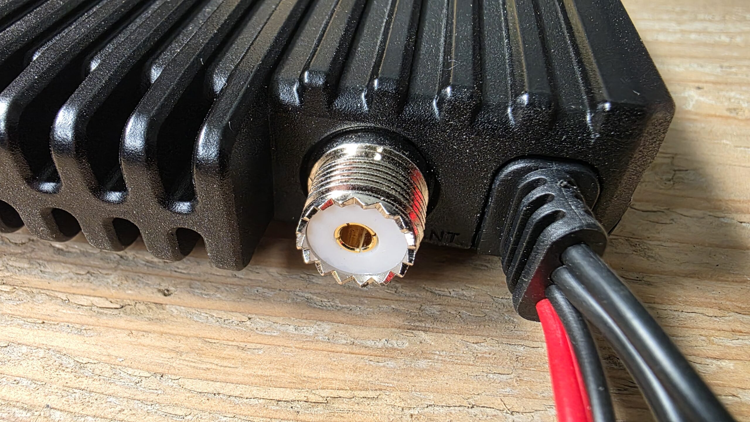
| RG-58/U | approx. 11–13 dB | CB radio, short runs up to approx. 10–20 m | PL-259 for RG-58 | SO-239 (UHF socket) |
| RG-213/U | approx. 5–6 dB | Fixed CB and amateur radio installations | PL-259 for RG-213 | SO-239 (UHF socket) |
| Aircell 5 | approx. 8 dB | Mobile and compact installations | PL-259 or N plug | SO-239 or N socket |
| Aircell 7 | approx. 5 dB | High-quality fixed installations | PL-259 or N plug | SO-239 or N socket |
| Ecoflex 10 | approx. 3.8 dB | Longer runs with low attenuation | PL-259 or N plug | SO-239 or N socket |
| H-155 | approx. 7–8 dB | Mobile radio installations and short base-station runs | PL-259, BNC, N or SMA | SO-239, BNC, N or SMA socket |
| RG-174/U | approx. 22 dB | Short links inside the device | SMA, BNC or Mini-UHF | Matching mating socket |
Note: All the coaxial cables listed have a characteristic impedance of 50 Ω and are therefore suitable in principle for CB radio and other 50 Ω HF applications. They mainly differ in their attenuation, flexibility and permissible bending radius.
Common connectors in CB radio
| Name | Description | Typical use |
|---|---|---|
| PL-259 | UHF plug (coax plug) | Standard plug on CB sets and antenna cables |
| SO-239 | UHF socket | On radio sets, antennas and test equipment |
| PL-258 | UHF coupler (socket-to-socket) | For joining two PL-259 plugs |
| N plug | 50 Ω HF plug | Professional radio work, low losses |
| N socket | Matching socket for the N plug | Base stations and test equipment |
| BNC | Bayonet connector | Test equipment and lab applications |
| SMA | Compact screw connector | Handheld radios, Wi-Fi and GPS |
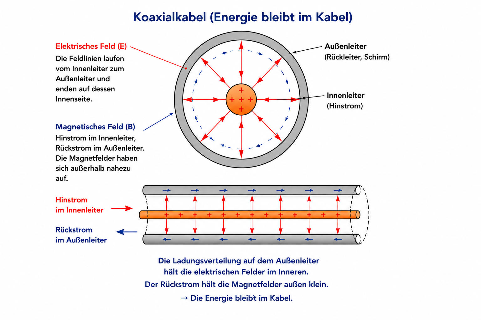
Why do the signal and the energy stay trapped in the coaxial cable?
If you want to know exactly why the energy, and with it the radio signal, can’t leave the coaxial cable, read on for a moment.
For that you need to look at the construction more closely. The inner conductor and the outer conductor are at different voltage potentials and they sit close opposite each other. The outer conductor ideally keeps its potential, let’s say 0 volts. In high-frequency engineering it’s preferred to talk about the return conductor rather than ground or the negative pole. The inner conductor carries the HF signal. There the polarity changes constantly. So it’s from the inner conductor that the electric fields arise, holding the energy being carried. They spread out radially as far as the outer conductor and only as far as the outer conductor. This is different from the antenna now. There this “counter-pole” doesn’t exist, which is why the waves carry on out into space.
The outer conductor of a coaxial cable acts like a Faraday cage for the electric field from the inner conductor. The charge distribution caused by the inner conductor holds the electric field lines between the inner and outer conductor, while the equally large return current in the outer conductor almost cancels out the magnetic fields on the outside. That’s how the electromagnetic energy stays in the coaxial cable.