




You now know where the high-frequency alternating-voltage signal comes from and how it reaches the antenna. Now it has arrived at the antenna, and the antenna is worth a chapter of its own. So follow the signal into the radiator.
Our little series on CB radio, still an essential means of communication when it comes to off-road driving and travelling in convoy, has now reached its second part.
Here is the first part: CB Radio: The Basics of Transmitting (1/3).
The basis for a transmit signal
When transmitting, an electromagnetic oscillation builds up in the antenna system. The antenna forms a system capable of oscillating, in which energy is exchanged between the electric and the magnetic field. If the antenna is resonant, the frequency of the transmit signal matches its natural frequency. This lets the current and voltage distribution take on a particularly favourable shape, and the antenna can radiate the supplied high-frequency energy especially effectively. It works much like a swing that is always pushed at exactly the right moment, so that it swings higher and higher.

What are electric and magnetic fields?
If you have a piece of metal, for example a conductor like an antenna, and you apply a voltage to it, you change the electrical potential of that conductor relative to its surroundings. This creates an electric field, because there is now a difference in potential between the conductor and its surroundings. Those surroundings can simply be the environment, the earth or another conductor.
Electrical potential can be compared to the water level at a dam. The height of the water surface corresponds to the potential. As long as the dam is closed, no water flows. Even so, because of the different water levels on the two sides, there is a force that would make the water flow. If you open the dam, water flows until the levels have equalised. Once that is reached, the potential is the same on both sides again. The difference between the two water levels corresponds to the electrical voltage, the difference in potential. The flowing water would be the current.
If a current flows through the conductor because of this voltage, electric charges move. This movement of charge also creates a magnetic field that forms in a ring around the conductor.
Put simply: the voltage, or the separation of charge, creates the electric field, and the flowing current creates the magnetic field.
With alternating voltage, voltage and current change constantly, and so do the electric and magnetic fields. The changing magnetic field in turn creates an electric field through induction. The other way round, a changing electric field also creates a magnetic field. This interaction is the basis for the propagation of electromagnetic waves.
Let’s sum up:
When a voltage is applied to a conductor, the difference in potential to the surroundings creates an electric field. If current also flows, the moving charges create a magnetic field around the conductor. With alternating voltage, voltage and current change constantly, and so do the electric and magnetic fields. The changing magnetic field in turn creates an electric field through induction.
Length, design and resonance
Whether an antenna is in resonance at a particular frequency depends above all on its length and its design. For a simple straight antenna, the length needed is in a fixed ratio to the wavelength lambda λ of the radio signal. Antennas with a length of λ/4 or λ/2, for example, can be resonant. In CB radio that would be 2.75 or 5.5 metres, rather impractical lengths.
Alongside the physical length, people therefore also talk about the electrical length of an antenna. It describes what fraction of the wavelength the antenna corresponds to electrically. The design can change this ratio. Coils, capacitive elements, the diameter of the antenna rod or the arrangement of the conductors all affect the electrical properties of the antenna. This means a physically shorter antenna can behave electrically like a longer one and be resonant.
What matters for resonance is therefore not the physical length measured with a folding rule alone, but the electrical length, which comes from the physical length and the design of the antenna. This way the antenna can be kept physically shorter while its electrical length still matches the length needed for the desired frequency.
The λ/2 dipole, the mother of all antennas
The dipole is one of the simplest and at the same time most important antenna forms. The way many other antennas work can be traced back to it. A classic half-wave dipole (λ/2 dipole) consists of two separate radiators, each roughly a quarter of the wavelength long. Together they have an electrical length of half a wavelength.
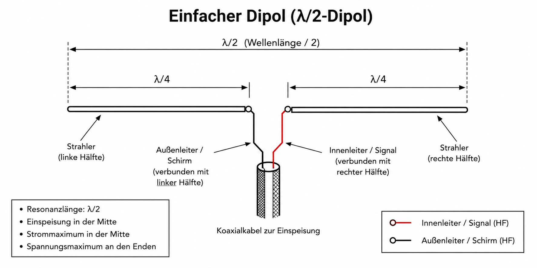
Dipole antenna
The two radiators are fed with the radio signal at the centre of the dipole. When a coaxial cable is used, the inner conductor is connected to one dipole half and the outer conductor, or shield, to the other. The two dipole halves themselves have no direct conductive connection to each other. The radio signal’s alternating voltage from the radio sits between them.
At resonance, a characteristic distribution of current and voltage builds up along the dipole. The current maximum is at the centre and the voltage maximum at the two open ends. No current can flow on at the ends, which is why the current there drops towards zero. At the same time electric charges can build up there, so the voltage reaches its maximum.
Feeding in the middle is especially favourable. There the ratio of voltage to current is comparatively small. A theoretical λ/2 dipole located freely in space has an impedance of about 73 ohms at the feed point. That already puts it fairly close to the 50 ohms common in radio technology. In practice, though, the impedance is affected by, among other things, the setup, the height above the ground and the surroundings.
Another advantage of the dipole is its symmetrical design. Both radiators together form the antenna and serve as each other’s counterpole. Unlike a λ/4 antenna (see further below), the dipole therefore needs no additional conductive ground plane as a counterpole (also called a counterpoise or mirror).
The length of λ/2 should not be taken too literally as a purely mechanical length. What matters for resonance is the electrical length of the antenna. Because of conductor diameter, design, the materials used and the surroundings, the physical length actually needed can differ from λ/2. A real half-wave dipole is therefore usually a little shorter than the calculated half wavelength.
For CB radio at around 27 MHz, the wavelength is about 11 metres. A λ/2 dipole would therefore be roughly 5.5 metres long on paper, with about 2.75 metres per dipole half. The exact length is then tuned so that the antenna is in resonance at the desired frequency.
The λ/2 dipole thus combines a very simple design with high efficiency and properties that are easy to calculate. For that reason it works well as a real-world antenna, and it also makes an ideal basic model for understanding how radio antennas work.
From the dipole to the vertical radiator
The λ/2 dipole consists of two radiator halves that work together electrically. Together they form the antenna system and make possible the current and voltage distribution needed for radiation. In doing so, the halves form each other’s counterpole. That is why a freely suspended dipole needs no vehicle body or other ground plane as an additional counterpole.
With vehicle antennas, on the other hand, you normally want only a vertical radiator above the vehicle, that is, only one half of the dipole. Depending on the type of antenna, the necessary second part of the antenna system is realised in different ways. This is exactly where a key difference between the various designs lies.
That brings us to the three common antenna types you will find in the shops: λ/4, λ/2 and 5/8 λ antennas. What do these names mean and where are the differences?
λ/4 antenna
The λ/4 radiator needs a counterpole. Put simply, it corresponds to one half of the λ/2 dipole. The vertical radiator forms one side of the antenna system, the vehicle body the other. The inner conductor of the coaxial cable is connected to the radiator at the antenna base, the outer conductor to the body. The body is therefore not just a mechanical mount or an electrical earth, but a functional part of the antenna system.
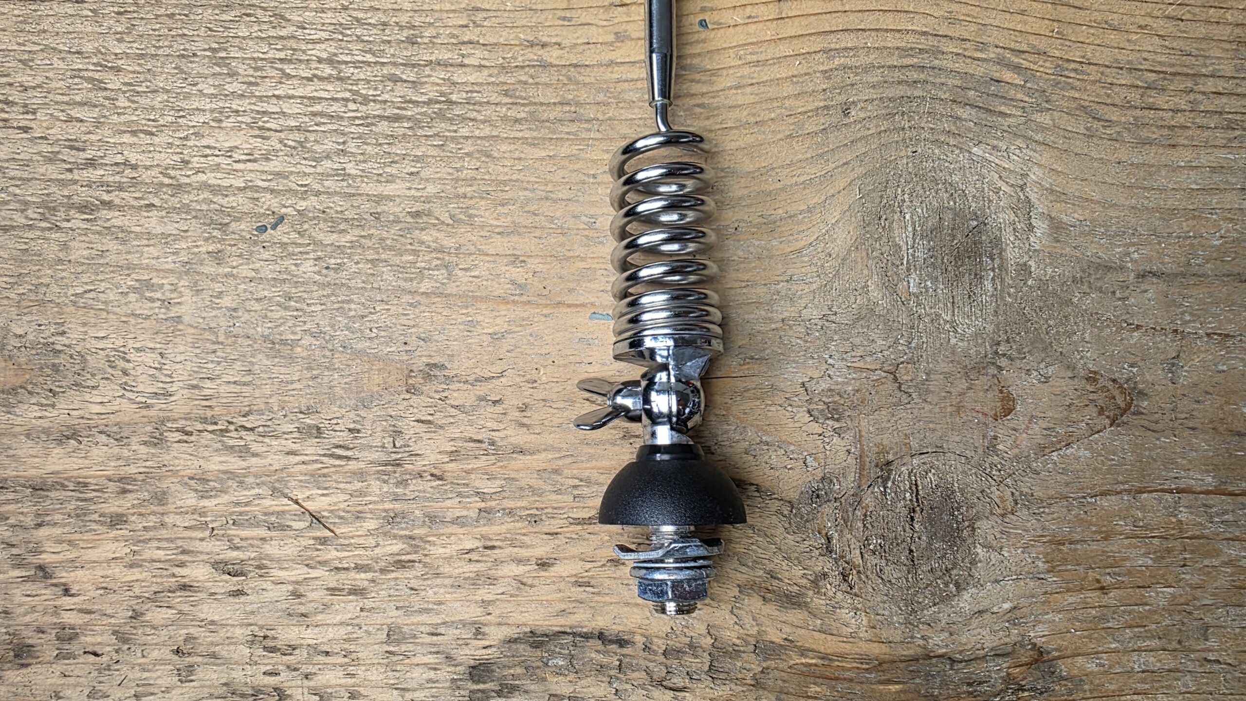
Feed point of the 1/4 λ antenna Albrecht Gamma 2F.
λ/2 antenna
A λ/2 radiator works differently. The radiator itself already has an electrical length of about half a wavelength. It therefore needs no ground plane like the λ/4 antenna or the 5/8 λ antenna. However, a λ/2 radiator cannot simply be connected to the 50 ohm coaxial cable. At its end it has a very high impedance. In the antenna base there is therefore a matching circuit, for example a coil or a transformer element, which matches the high impedance of the radiator to the much lower impedance of the coaxial cable.
High-quality designs try to control these conditions deliberately. So when you read “no counterpole required” in the description, for a λ/2 antenna it means: it needs no ground plane. That makes it particularly suitable for boats and other vehicles made of plastics, fibreglass and so on.
5/8 λ antenna
In its classic form, the 5/8 λ radiator needs a counterpole, or a ground plane. Its electrical length of 5/8 λ also means that its impedance at the base does not directly match a 50 ohm coaxial cable. That is why there is an additional matching circuit in the antenna base, usually with a coil. On a vehicle antenna, the body again takes on the role of the counterpole.
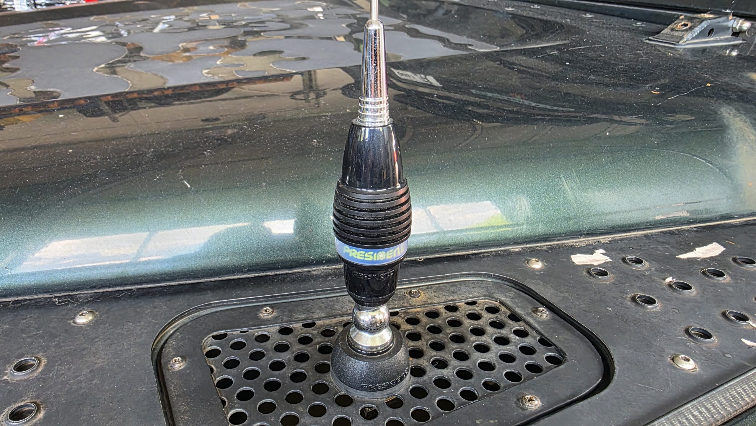
Feed point of the 5/8 λ antenna President Oregon.
Bandwidth
A word on bandwidth. Bandwidth is the frequency range within which an antenna keeps certain desired properties. With CB radio, bandwidth is often looked at together with the standing wave ratio, that is, the frequency range in which the standing wave ratio stays below a certain limit. The more broadband an antenna is, the more frequencies it can cover well.
CB radio has a bandwidth of about 840 kHz (26.565 to 27.405 MHz). German CB radio has 80 channels available with a channel spacing of 10 kHz; the voice channels considered here can be used with FM. There really are antennas that do not cover the whole range optimally.
- Channels 1 to 40: 26.965 to 27.405 MHz
- Channels 41 to 80: 26.565 to 26.955 MHz
Channels 41 to 80 were released after the first 40 channels and sit below them in frequency. Anyone who mainly uses the first 40 channels should choose an antenna whose frequency ranges lie there.
Antennas can usually still be adjusted within limits (more on that in the third part on the standing wave ratio), so an antenna with a narrower bandwidth can also work well, as long as it covers your chosen channel and its frequency. Channel 16 (4×4 = 16), popular with off-roaders, sits at 27.155 MHz in Germany.
As a rule of thumb: the more an antenna is electrically shortened, the lower its bandwidth tends to be.
The three most common CB radio antenna types
This gives three fundamentally different cases:
| Feature | λ/4 radiator | λ/2 radiator | 5/8 λ radiator |
|---|---|---|---|
| Typical form on the vehicle | usually shortened | practically always clearly shortened | practically always clearly shortened |
| Technical feed arrangement | inner conductor to the radiator, outer conductor to the vehicle body | inner conductor to the radiator via a matching network; the second electrically effective side is created by the antenna construction | inner conductor to the radiator via a matching network, outer conductor to the vehicle body |
| Counterpole on vehicle mounting | vehicle body or a suitable conductive surface | no large vehicle surfaces required; handled within the antenna system by design | vehicle body or a suitable conductive surface |
| Role of the body | an essential part of the antenna system | far less decisive | an essential part of the antenna system |
| Feed-point impedance of the idealised basic form | about 36 Ω over an ideal ground plane | very high impedance, typically in the kΩ range | not directly suited to 50 Ω without matching |
| Matching to 50 Ω (already done by the maker) | relatively simple | absolutely necessary | necessary |
| Suitability for fibreglass/plastic bodies | only with a suitable counterpole | very good | only with a suitable counterpole |
| Idealised radiation | good flat vertical radiation | typical vertical omnidirectional pattern | a flatter radiation angle possible under ideal conditions |
| Polarisation with vertical mounting | vertical | vertical | vertical |
| Dependence on correct vehicle mounting | high | lower as regards the ground plane | high |
Pros and cons
| Radiator type | Advantages | Disadvantages |
|---|---|---|
| λ/4 radiator |
|
|
| λ/2 radiator |
|
|
| 5/8 λ radiator |
|
|
The mounting location
Besides the choice of antenna type, the mounting location on the vehicle also has a considerable influence on how well a CB radio antenna works. It is not just about mounting the antenna as high as possible. The mounting location affects both the electrical tuning of the antenna and its radiation.
As a basic rule, an antenna should be mounted as high and as free as possible. The fewer large metal parts there are right next to the radiator, the less the antenna’s electromagnetic field is affected. Mounting on the vehicle roof therefore usually offers good conditions. The radiator sits largely free and, with a λ/4 or 5/8 λ antenna, can at the same time use a large conductive roof surface as a ground plane or counterpole.
On off-roaders and travel vehicles, though, roof mounting is not always possible or sensible. Roof tents, pop-up roofs, roof racks or the overall height of the vehicle can be reasons against it. That is why CB antennas are often mounted on the bull bar, the wing, the spare-wheel carrier or on the side of the vehicle. Such locations can work well, but they create different conditions for the antenna.
If large vehicle parts are right next to the radiator, they affect its electromagnetic field. This can distort the radiation. A vertical antenna that, under ideal conditions, radiates roughly evenly in all directions in the horizontal plane can then favour or disadvantage certain directions. With an antenna on the front bull bar, for example, a large part of the vehicle is behind or beside the radiator. You could loosely call it shadowing, but in fact it is an effect on the whole electromagnetic field caused by the conductive vehicle parts.
The height of the free radiator also plays a part. If a long antenna is mounted low on the wing, so that a considerable part of the radiator runs alongside the body, the effects are greater than if almost the whole radiator sits above the vehicle roof. As a simple rule of thumb: the more of the radiator that projects freely beyond the vehicle’s outline, the more favourable the conditions for radiation tend to be.
The resulting counterpole matters too
For antennas that need a ground plane as a counterpole, there is one more point. A mechanically solid mount alone is not enough. The antenna base, or the outer conductor of the coaxial cable, must have a connection to the intended ground plane that works at high frequency. Paint, powder coatings, plastic parts or body parts that are poorly connected to each other can mean that a seemingly good mounting surface forms no suitable electrical counterpole at all. With a suitably designed λ/2 antenna this point is less critical, because it needs no large conductive vehicle surface as a counterpole.
The mounting location also affects the feed-point impedance and the resonant frequency. An antenna that was correctly tuned in free space can behave differently once mounted right next to the body, a roof rack or other metal parts. The final tuning of a vehicle antenna should therefore always be done after it is fully mounted in its intended place. Accessories in the immediate vicinity of the antenna can play a part here too.
For the choice of mounting location, this gives a simple order of priority: as high as possible, as free as possible and, if the antenna type needs a ground plane, with a suitable counterpole. An electrically perfect antenna can only show its theoretical properties if its surroundings are right too.
The most convenient position on the vehicle is therefore not necessarily the best one for radio. On off-roaders in particular, you often have to find a compromise between radiation, vehicle height, protecting the antenna, mechanical load and everyday practicality. An antenna on the bull bar, for example, can protect the roof from damage very well and be easy to reach, while roof mounting usually offers the better conditions from a radio point of view.