



If anything gets the blame for poor transmit performance in CB radio, it is the standing wave ratio, the SWR. It gets measured quickly, then perhaps tuned a little better, and then all is well. Is that really so? And what does the standing wave ratio even mean? Welcome to the third and final part of our little series on radio technology.
Wow! You have stuck with us to the third part. You now have the radio, cable and antenna fitted in your off-roader. Bring on the off-road park, and the trip with five other vehicles too. Right? Are we done already? Not quite.
Reading our little series for the first time here? If so, have a look at parts 1 and 2 as well.
Part 1 is here: CB Radio: The Basics of Transmitting (1/3)..
Part 2 is here: CB Radio: Antennas (2/3).
The story so far: the radio generates a high-frequency alternating voltage, the radio signal, onto which speech is modulated. It is sent through a coaxial cable and (hopefully) radiated cleanly and strongly. For that to work, a few mounting and environmental parameters have to be right. So far, so good. How and why an antenna transmits, and which antennas you commonly find in CB radio, was covered in part two. The signal has, so to speak, arrived at the antenna and is being radiated. That is the starting point for this third and final part.
It is about the standing wave ratio. An effect that deserves an article of its own, if only because it gets described and debated so often. And when the standing wave ratio is good, everyone is happy. But part two already hinted that the SWR cannot be held solely responsible for good transmit performance, and that antenna type, mounting position and the surroundings play a part too.
Now, though, let us get to the main character of part three.
The standing wave
One thing can be said for certain: at heart, no radio operator wants a standing wave. In the end it means that not all of the power sent out by the radio can potentially be radiated by the antenna. Part of it is reflected at the antenna feed point and travels back to the radio. “Potentially can”, because whether what reaches the antenna is actually radiated is answered at the end of the article.
It should also be said here that a standing wave like this can form at any transition from one electrical conductor to another, and even within a conductor, not just at the cable-to-antenna transition, the antenna feed point. For us, though, the transitions from the radio to the cable and from the cable to the antenna are the interesting ones.
So why is it called a standing wave? Have a look at the animation a little further down. You see a wave running towards the antenna (red), your radio signal. With an SWR of 1 there is no returning wave or power, and therefore no standing wave. If you push the slider for the reflection coefficient to the right, that shows a less than ideal match, and as a result part of the power is reflected. The blue returning wave and the resulting black wave made of both signals, the standing wave, appear. At some point the reflection is so strong that this wave almost stands still, hence the term standing wave.
With this animation you can try it out for yourself. First set the speed so you can follow the waves nicely. With the slider for the reflection coefficient you can go from 0 (SWR = 1, no reflection, no standing wave, only a forward wave) to 1 (SWR = ∞, full reflection, maximum standing wave). You can then watch how the standing wave (black) behaves. The standing wave ratio from 0 to infinity (∞) is shown to you as you do.
The standing wave ratio, SWR
The animation has probably already made clear what the standing wave ratio tells you. The standing wave ratio (SWR, standing wave ratio) describes how strongly a forward wave and a reflected wave overlap on a line. It is given as the ratio of the largest to the smallest voltage value occurring along the line:
SWR = voltage Umax / Umin
That also makes clear that an SWR of 1:2 cannot exist, because the value expresses a ratio that can be at least 1, or greater than 1 up to infinity, and since by definition Umax is always greater than Umin, there can be no value below 1. So it would be 2:1. Just to say it clearly here, and for the beer-garden debates. Now you can win the argument with this knowledge.
The ideal, then, is an SWR of 1:1 = 1. There is no reflected power. In practice that is likely to be rare, as explained in part two and in the text that follows here.
How the standing wave forms
The question that follows is: how does the reflection, and with it the standing wave, come about? That is easy to answer. When the signal meets an impedance that does not match the line so far, part of the signal is reflected. This is usually the case at the transitions: radio to cable and cable to antenna. As a reminder from part 2, the impedance in CB radio should be 50 ohms throughout.
You will remember that the individual antenna types deviate more or less from the 50 ohm impedance that the radio and cable are set to. The antenna maker then matches the feed point as well as possible, but the surroundings and mounting position of the antenna take it away from the ideal value again. That is why antennas can still be adjusted afterwards, within limits, by you.

Reflection and standing wave
A good comparison here is a long rope, with which we can explain the three possible states of a coaxial cable: open, short-circuited and with an antenna (load). Imagine you flick a wave (signal) into the rope (cable) with your hand (radio).
If the rope is open and free at the end, it cannot get rid of the energy you put in. All the energy comes back to your hand (reflection). That is the “open” case, when you have no antenna connected to the cable to draw the energy out of the line and use it. This is dangerous for the radio, because the output stage gets the full power back. The SWR is infinitely high. Modern sets protect themselves by immediately turning the power down. For that reason you should never press the transmit key without an antenna connected.
In the second case the rope is tied off stiff and rigid at the end. That describes the case of a short circuit. Here too the rope cannot get rid of the energy, because the connection at the end does not move with it. Again all the energy comes back, because the rope has to shed it. In radio the signal is likewise reflected 100 percent, the SWR is again infinitely high.
The animation shows these two situations when you set the slider all the way to the right. The open cable end is shown when the red and blue waves lie on top of each other and the black curve is at its highest; the short circuit matches the picture when the red and blue curves are offset by 180 degrees.
In our comparison, the ideal case has a damper (antenna) at the end of the rope that is perfectly matched to the rope and your wave. The end of the rope can swing exactly in time with and at the intensity of the wave, and because the damper moves with it, it takes exactly the energy out of the rope that you put in. So you have a clean wave, with no counter-running waves coming back to your hand. For the radio signal that means the antenna takes up the electrical power completely and, ideally, radiates it too. The SWR is then 1:1.
The normal case would match a damper that does not work quite perfectly and lets a small part of the energy run back into the rope.
Measuring the standing wave ratio, what you measure and why
Now it is about measuring your standing wave and, where possible, improving it. For that you need a standing wave meter. We recommend the Albrecht SWR-30*.
With the standing wave meter, which shows you exactly the ratio, you can measure two different things. On the one hand you can learn something about the quality of the system behind the radio. How much power comes back to the radio? At first it does not matter whether the cable or the antenna is the cause. This is the first measurement you should make, because if the SWR is already poor here, you are putting the radio at risk. Then you first have to sort out the cable and the antenna.
The other measurement you take between the end of the cable and the antenna base. With it you can find out how well the antenna is matched to the 50 ohm impedance. But, as said, it says nothing about how much power the antenna actually radiates. You only see how much power reaches the antenna.
Taking measurements
For simplicity we split the measurements into two areas. First: quick & dirty, you just want to check whether your installation gives at least a usable SWR. Second: you want to know more precisely.
Let us start with “first”. You have everything installed and now want to tune the system as well as possible. For that you need a simple SWR meter, like the one we recommended. Now you have to decide something for yourself: which channel or channels do you transmit on? If you only use channel 16 (27.155 MHz), you can carry out the measurement and tuning just for that channel. If you use other channels, for example 9 and 16, the tuning should take both into account.
For all measurements the SWR meter is connected between the radio and the cable. Follow the instructions for your meter.
As a rough guide you can use this classification for the results:
- SWR ≤ 1.5: very good
- 1.5 to 2: still usable, you can try to get it a little better with the antenna adjustment
- 2 to 3: here you should adjust in any case
- 3: find the cause, not usable like this
Very important: reaching an SWR of 1.0 is not the absolute goal. If you have it, great, but it also works very well with a slightly higher SWR.
Simple SWR measurement for one channel
Set the radio to channel 16 FM (16 because 4×4 = 16. In any case the channel you want to use). Calibrate the meter as described in the manual. On simple meters like the SW-30 from Alan, you set the switch on the front to “FWD” (forward) and hold down the transmit key. Now you have to use the knob to move the needle to the end of the scale where it says “SET”. On other meters you will also find the “∞” symbol there.
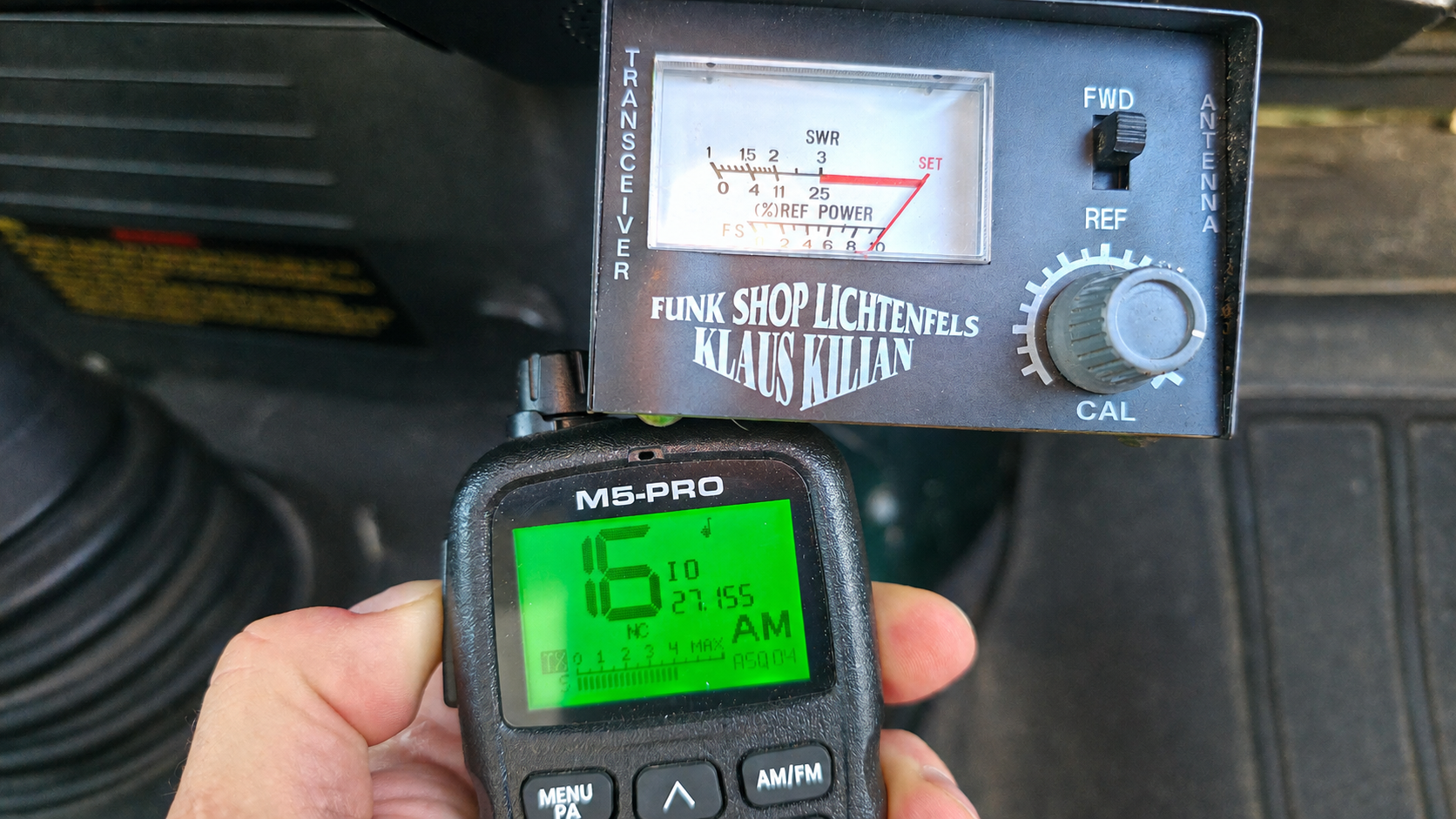
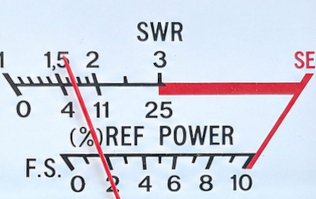
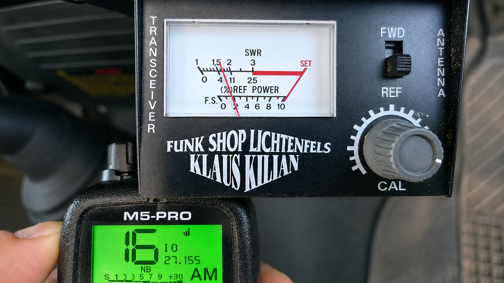
Then switch to “REF” without letting go of the transmit key. Now the SWR is shown.
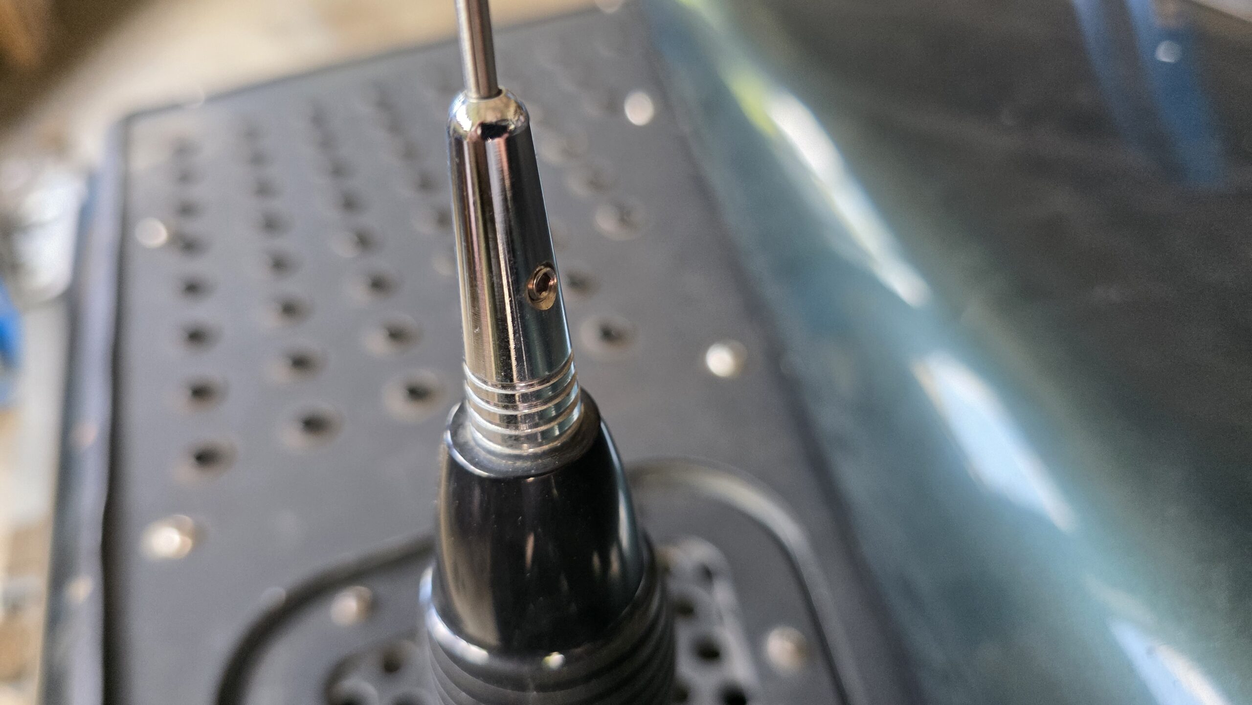
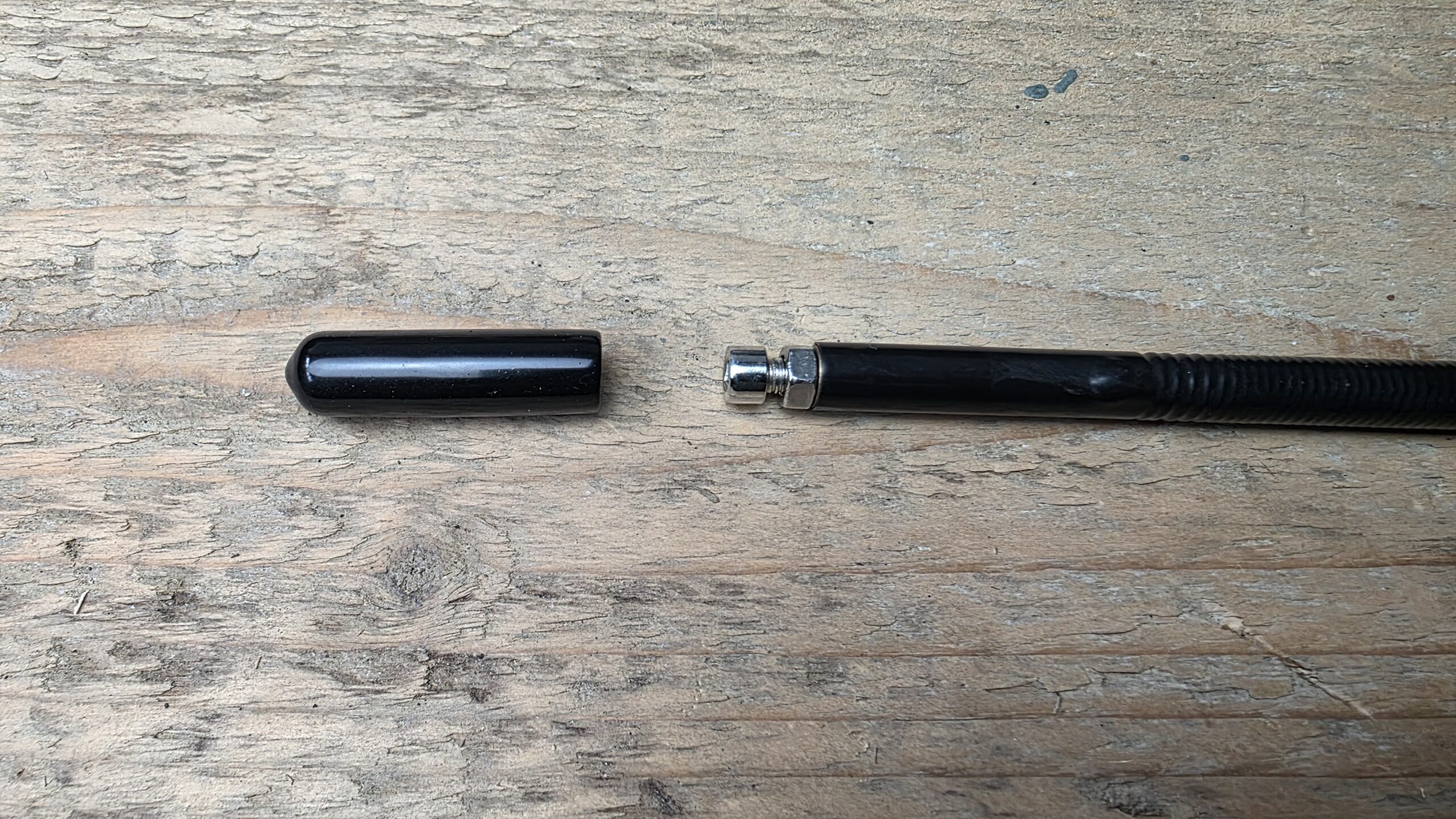
If an adjustment is needed, you only have to modify the antenna. As a rule that works by changing the length. Check your antenna’s manual for how to do it. Often there is a screw in the base that fixes the radiator, or there is a screw under a cap at the top of the antenna. If you want to know whether you need to shorten or lengthen the antenna, a measurement over two channels is needed, as described below. If that is too much effort for you, simply try out what happens when you lengthen or shorten it.
Simple measurement for more than one channel
Since the SWR changes with frequency, with several channels that you transmit on you have to find the middle setting. With a measurement across several channels you can also see whether the antenna needs to be lengthened or shortened in each case.
You now carry out the measurement as described above for, say, channel 9 and channel 16 and write down the respective SWR.
- SWR channel 16 < SWR channel 9 = the resonance tends to be too high, the antenna should be lengthened a little.
- SWR channel 16 > SWR channel 9 = the resonance tends to be too low, the antenna should be shortened a little.
Then measure again and keep closing in. It might look like this, for example:
| CH 9 | CH 16 | |
|---|---|---|
| Starting state | 1.8 | 1.3 |
| after adjustment 1 | 1.5 | 1.2 |
| after adjustment 2 | 1.3 | 1.2 |
| after adjustment 3 | 1.2 | 1.3 |
With values like these you can leave it be.
Tuning across all channels of the radio
If you want to get the best out of the radio across the whole channel bandwidth, or want to see the antenna’s characteristic, you need more measurements. Bear in mind that there are frequency jumps between the channels. The order from the lowest frequency to the highest would therefore be, as an example for nine measurement points:
- Channel 41: 26.565 MHz
- Channel 52: 26.670 MHz
- Channel 62: 26.755 MHz
- Channel 72: 26.880 MHz
- Channel 3: 26.985 MHz
- Channel 12: 27.090 MHz
- Channel 24: 27.195 MHz
- Channel 34: 27.300 MHz
- Channel 40: 27.405 MHz
You can of course also choose larger intervals and fewer measurement points, or include your primary transmit channel in the measurement to find the exact value for that channel. In the example there are now nine measurements, each 105 kHz apart in frequency. Again, note down the SWR and the channel for each measurement. Draw a curve from it, for example in Excel.
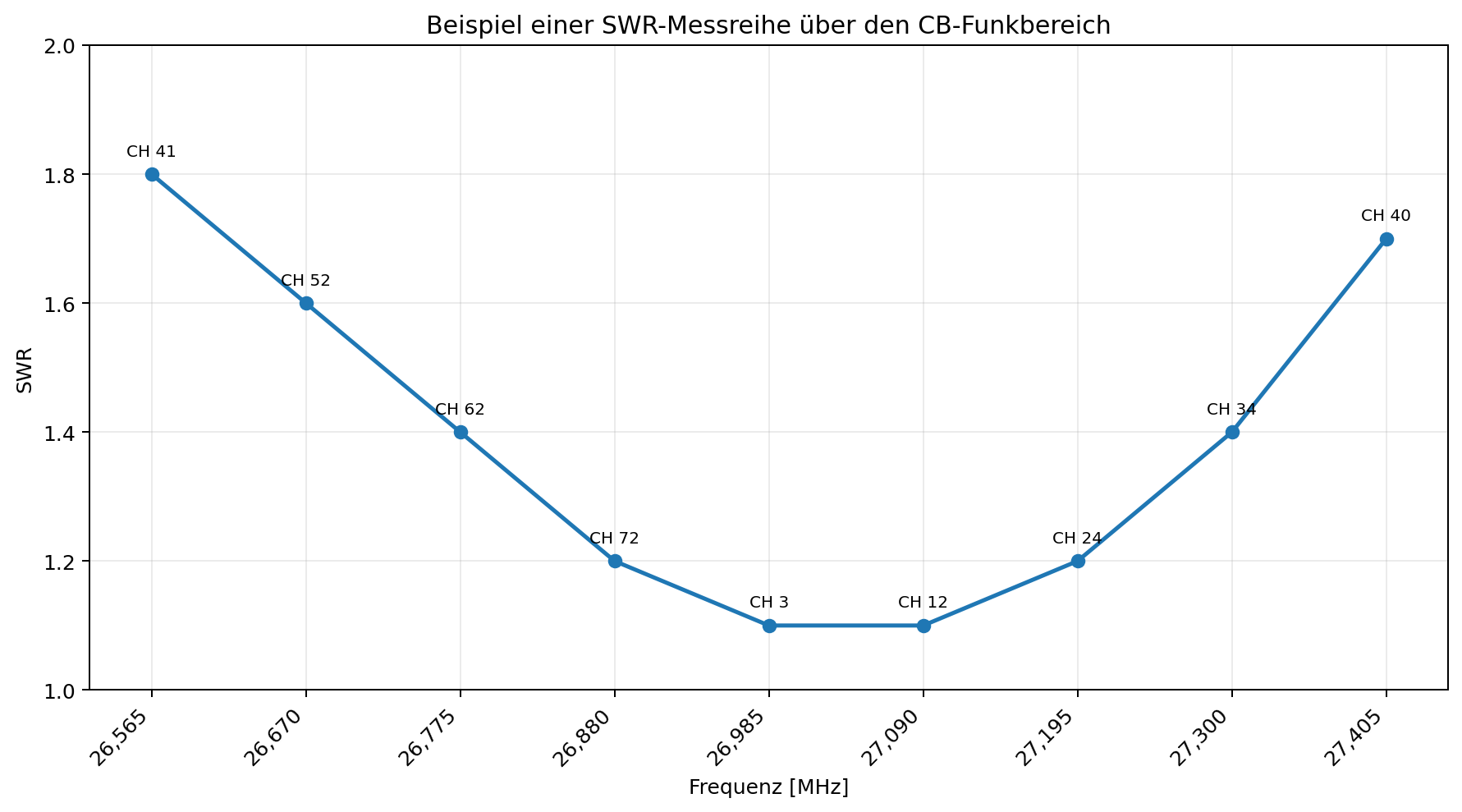
What you now see shows which frequency the antenna is currently tuned best for. From this curve you can read that the antenna is well tuned for the middle frequencies of the CB range. In this case at channels 3 and 12, because that is where the SWR is lowest. Our channel 16 lies between channel 12 and 24, so it would have an SWR < 1.2, and that would be very good. There would be no need to change anything.
If your primarily used channels do not sit so well, you have to work out which way the antenna needs to be adjusted. The rule here is:
| SWR minimum | Antenna |
|---|---|
| Primary channel below the desired frequency | shorten |
| Primary channel above the desired frequency | lengthen |
If you wanted to use channel 52, you would have to shorten the radiator of your antenna, that is, push it further into the base. For channel 34 it would be the other way round, you would have to pull the radiator out a little.
Measurement at the antenna base
If you connect the meter between the cable and the antenna base, you can see what the antenna reflects, without the influence of the cable.
Does a good SWR solve every problem?
The answer is clear: no. If you have a good or even a very good SWR, the only thing it tells you is this: little or, at best, no signal power is thrown back, and the greater part or even all of it reaches the antenna feed point. Neither more nor less does a good SWR say. What the antenna does with it, the SWR does not say.
Just a short and understandable explanation for one of the possible reasons. Assume the antenna has an impedance of 50 ohms at the feed point. In an exaggerated sense that could also mean it has a radiation resistance of 10 ohms and a loss resistance of 40 ohms. In that case only the power represented by the 10 ohm radiation resistance would be transmitted, and the power of the loss resistance disappears. Only 20 percent of the power would be radiated, even though there is a perfect 50 ohm impedance at the feed point.
Now the opposite case. The antenna does not have a perfect impedance of 50 ohms, so part of the power goes back to the sender. But if 48 percent of that is radiation resistance and only 2 percent is loss resistance, the radiated power can be higher than with an antenna that has a perfect 50 ohm impedance.
That brings us to the efficiency of the antenna. It depends above all on the losses in the radiator, in the coils and matching networks, in contacts and connections, and on the design and surroundings of the antenna. Some of that is down to the design and is set by the maker. You can at least influence the quality of the contacts and electrical connections and the mounting position. That is something, at least.
Conclusion
By the end of the third part, all the essential things about transmitting with CB radio have been explained. We have barely spoken about receiving so far. On receive, a mismatch is less critical, because no significant transmit power has to be handled. For receive performance itself, though, antenna type, efficiency, mounting location and surroundings remain just as important. A well-working transmit antenna therefore usually also creates good conditions for receiving.
Let us sum up:
A well-working CB radio setup in the vehicle is not simply a powerful radio and any old antenna. The radio, coaxial cable, antenna, matching, mounting location and, depending on the antenna type, the vehicle body form a system that works together.
The radio expects an impedance of 50 ohms from the components that follow. The first component is the coaxial cable, which carries the signal to the antenna. So that as much of the signal as possible can be radiated, the antenna and feed line have to match each other as well as possible, that is, also have an impedance of 50 ohms.
A large deviation from that leads, especially at the transitions between the individual conductors, to a high standing wave ratio. The result is that part of the power runs back to the radio setup. If, the other way round, all the parts match well, as much as possible of the power delivered by the radio first reaches the antenna. How much of it is actually radiated then depends additionally on the efficiency of the antenna.
Which conditions have to be created at the antenna base to reach both the 50 ohm impedance and a high antenna efficiency also depends on the antenna type. A λ/4 radiator, for example, needs a suitable ground plane or a counterpole, which on a vehicle is usually formed by the conductive body. A suitably designed λ/2 mobile antenna, by contrast, relies much less on such a vehicle surface, but because of its high-impedance end feed it needs appropriate matching. The maker already takes care of that, though. A 5/8 λ radiator also needs matching and, in its classic form, a ground plane. On top of that, the quality and the location of the later mounting affect the actual feed-point impedance, which can then deviate from the desired 50 ohms again.
Since the theoretical radiator lengths for CB radio are often impractical on a vehicle, mobile antennas are mechanically shortened. Loading coils or helically wound radiators make sure the antenna can still become resonant at the desired frequency. This shortening is not without consequences, though: the more an antenna is mechanically shortened, the lower its efficiency and usable bandwidth can become.
That is why the longest antenna is not automatically the best, and the shortest not automatically the most practical. What matters is rather which antenna type suits the vehicle and the intended mounting location. A λ/4 antenna can be a very simple and efficient solution on a good metal surface. If a suitable conductive surface is missing, a λ/2 antenna designed for it can be the better and more flexible choice.
Even the best radio cannot make up for a badly chosen or badly mounted antenna. The other way round, a good antenna setup can get astonishingly much out of comparatively little transmit power. For a good CB radio setup in the vehicle, therefore:
Transmit power alone does not decide the range. What matters is how much of that power is actually radiated as a radio wave through the coaxial cable, the matching and the antenna. Choosing the right antenna type, a suitable mounting location and a clean tuning are therefore at least as important as the radio itself.
It is hard to give a range that a good CB radio setup should reach. So many factors feed into it. A perfect, stationary installation, with an antenna that cannot be used on vehicles, will surely reach 20 km, possibly more. But that cannot be a benchmark. Drawing on my own experience, which includes all the many small imperfect conditions, I would call a setup that reaches 5 to 7 km very good. Most, though, are likely to reach between 2 and 3 km. Buildings, hills, mountains and so on are simply obstacles. While built-up areas can mean both shadowing and signal reflection, the sources of interference increase in well-developed areas. In the desert, expect less range too, when the sand is very dry and therefore a very poor conductor. The ground is part of the radio system as well.
Some of it has been left out, reality is far more complex
It is clear that the deeper into the detail we go, the more complex it becomes. Then a whole pile of further technical terms, dependencies and so on come into play. Anyone who wants to get deeper into the subject is pointed to Karl Rothammel’s classic of radio technology, the “Antennenbuch”, if you can still get hold of a copy somewhere. Old, but physical laws and relationships do not change all that often.
If you are perhaps even aiming for an amateur radio licence, you will be “confronted” with these topics quite enough during your training. Worth recommending here is the site 50Ohm.de, a learning platform for aspiring radio amateurs.
For everyone else, the book “Antennen und Strahlungsfelder*” from Springer Vieweg is recommended (ISBN 978-3658499969). Springer Vieweg is an excellent source when it comes to technical knowledge.