Wherever a rotation has to be transmitted around an angle, two kinds of special joints are used. It’s either a universal joint or a constant-velocity joint. This article is about the universal joint, its properties and the key difference to the CV joint.
A universal joint is, for many, a simple piece of tech you don’t have to waste many thoughts on. A bit of grease here and there and that’s it. As long as your 4×4 is in its delivery state, that’s mostly the case. But once the modifications start at the latest and you lift the vehicle properly, this simple joint may move into focus.
Why that is, how it works and what particular feature it holds that can cause problems, you’ll read here. Plus a few tips on checking and servicing.
What a universal joint is for
The universal joint, also called a cross joint or simply U-joint, is used when a rotation including torque has to be transmitted around a bend. That is, the rotation “goes round the corner”. It also matters whether the angle changes dynamically or not. On the car it changes constantly, which we’ll go into in more detail. You’ll find universal joints on the propshafts, where this joint even gave its German name (Kardanwelle), and on driven, steered wheels. It’s also found in the steering, when the steering shaft has to bend to the steering box.
On the propshafts these joints are needed because the axle moves up and down, which changes the angle to the gearbox. On the driven, steered wheels they’re also found, because these likewise change the angle to the drive shafts when steering.
The use of universal joints isn’t set in stone, though, because there’s also the constant-velocity joint, also called CV joint. “CV” stands for “constant velocity”. What that means, we’ll explain.
The properties and limitations of the universal joint
Universal joints allow a rotation to be angled, and the angle can change during the rotation. This requirement exists in a huge number of technical devices, vehicles and machines. So far so good. Sadly the universal joint has a very unpleasant property that’s hard to impossible to grasp with the eye.
During a full rotation of 360 degrees, the angled side changes its rotational speed four times, it oscillates. While the side that gives off the rotation (drive) turns at even angular velocity, the other side (output) accelerates and brakes twice each. This is shown in the diagram below. While the drive (blue line) has the same rotational or angular velocity the whole rotation through, the output side leads twice and lags twice.
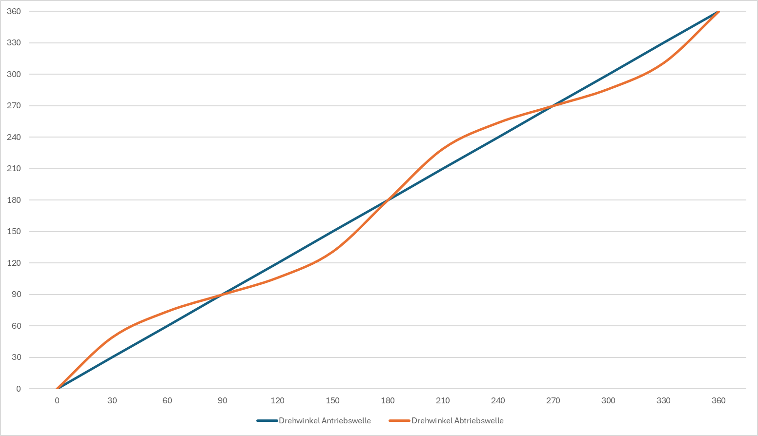
The size of the deviation depends on the working angle. In mechanical engineering, angles of 45° are accepted briefly. At this working angle the lead or lag is a difference of a good 10° of rotation! For continuous operation, 35° working angle should not be exceeded.
This so-called Cardan error causes strong vibration and eats energy. But luckily the first problem can be balanced out by a second universal joint. It’s arranged offset by exactly 90° (this is called “in phase”), which cancels the error at all times. The problem that remains is the uneven running of the shaft between the joints. That means the twice-over acceleration and braking uses energy and is still a source of vibration. So such shafts can’t be any length you like, they have to be calculated and designed precisely for the respective purpose.
The designers’ aim is to allow as even a transmission of the rotation as possible over the required angles at all times and at every angle. For that they have various design features available, which also affect the whole-vehicle concept, though. The type of axle location, for example, plays a role. In practice a good-enough compromise, or even an optimal solution, is then found.
Further factors go into the design of the joints and shaft. These include the rotational speeds and torques. These influence the design of the needle bearings of the cross joints, the diameter, length and material thickness of the shaft. All in all, this area alone is already very complex.
The conditions for even running
To achieve (as good as possible) even running with an angled Cardan connection, certain conditions have to be met. We’ll go into these individual points in more detail.
- To avoid uneven rotation, universal joints always have to be fitted in pairs –
An angled universal joint produces uneven running, the second smooths it out again. - The universal joints have to be in phase. –
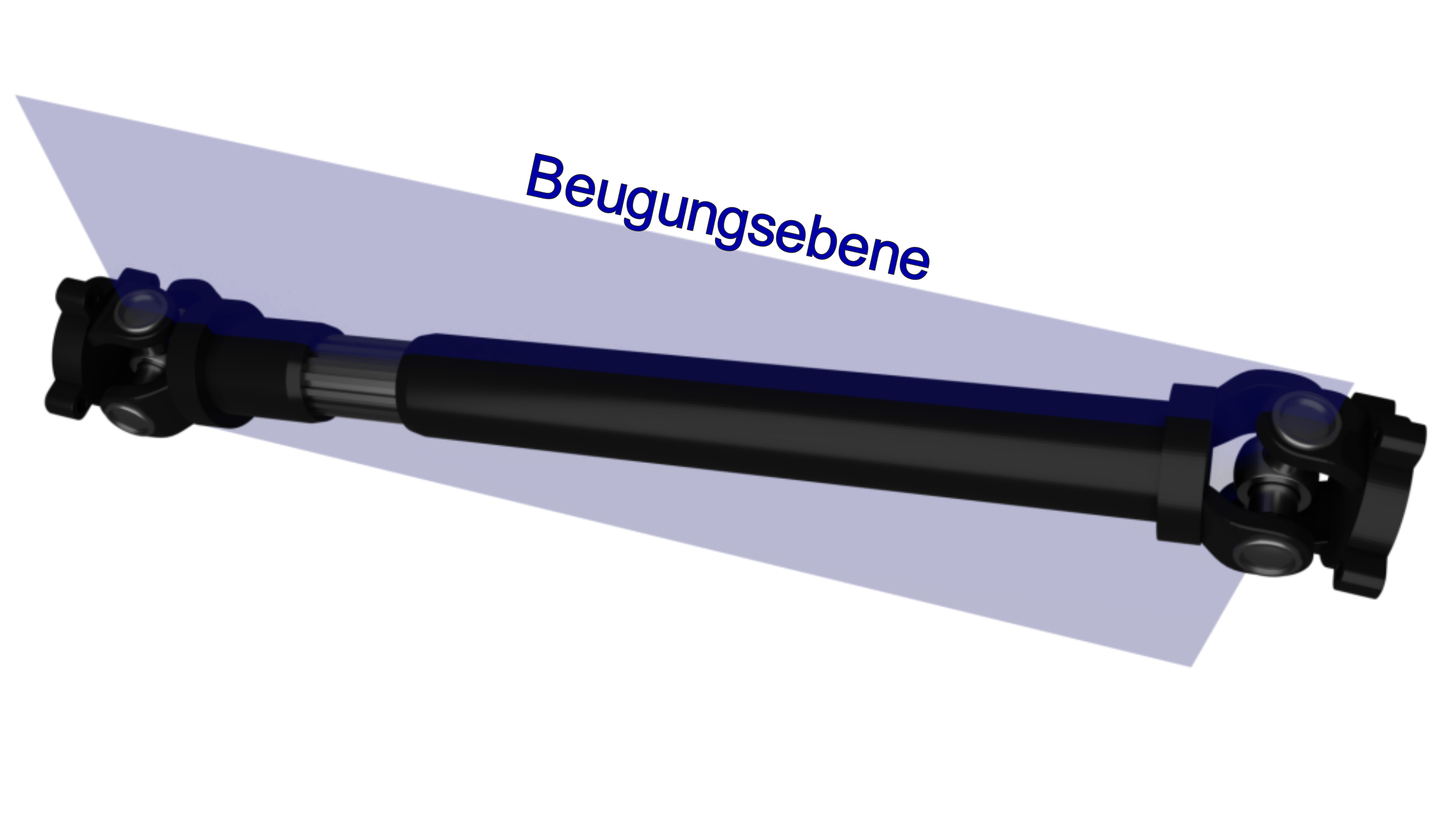
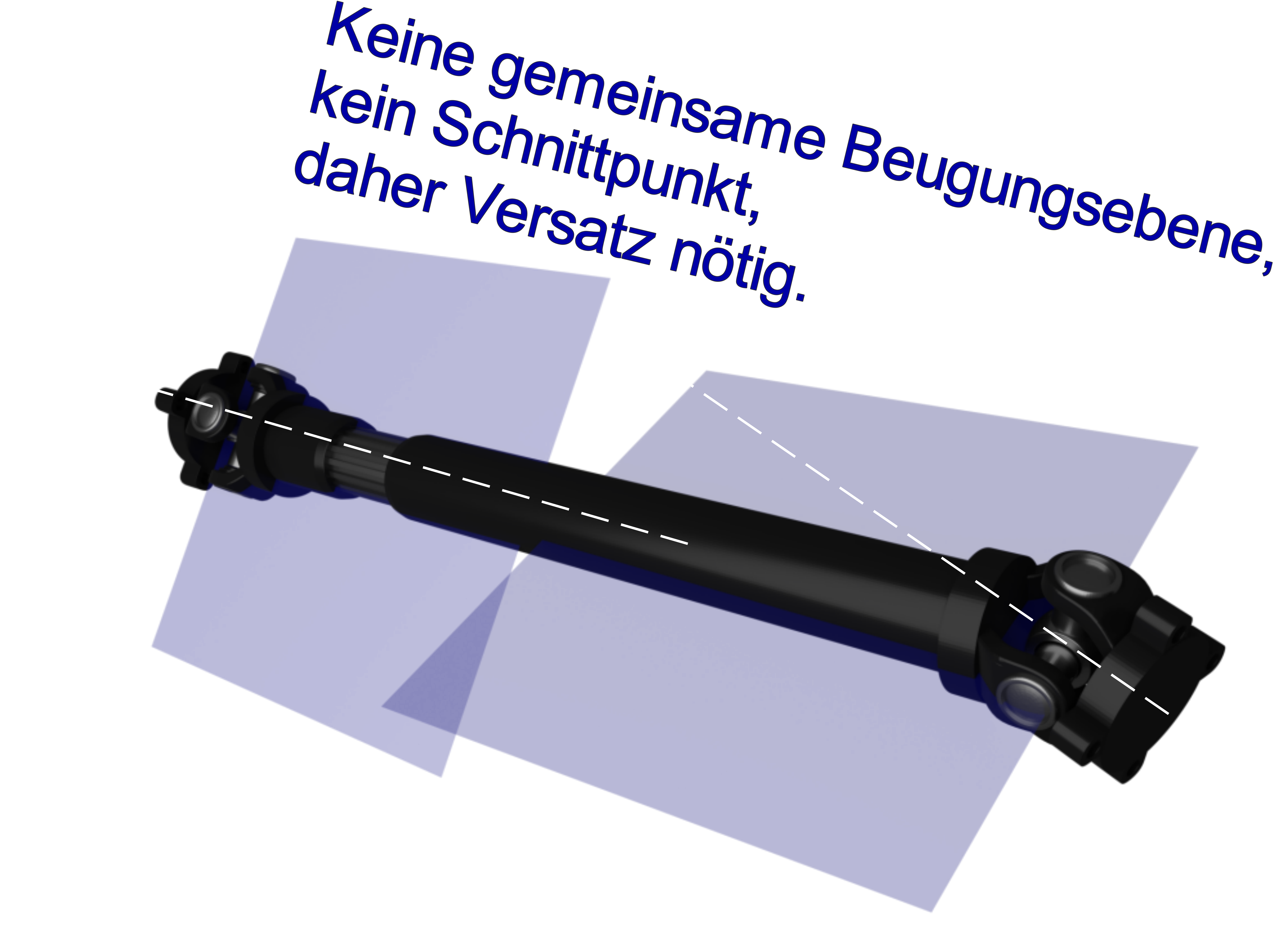
That is, the yokes of the respective force-giving sides have to be turned by 90°, or put another way, the yokes of the shaft sit the same. Why other angles can occur here is explained further below. - The bend of the joints has to lie on one plane. With the Z-configuration the output and input shafts have to lie parallel on this plane for that, with the W-configuration the shafts have to intersect. If neither applies because of a spatial offset, the phase has to be given an offset angle to compensate.
The basic forms
In vehicle construction, essentially two basic arrangements of Cardan connections occur, the Z and the W configuration.
Z-configuration
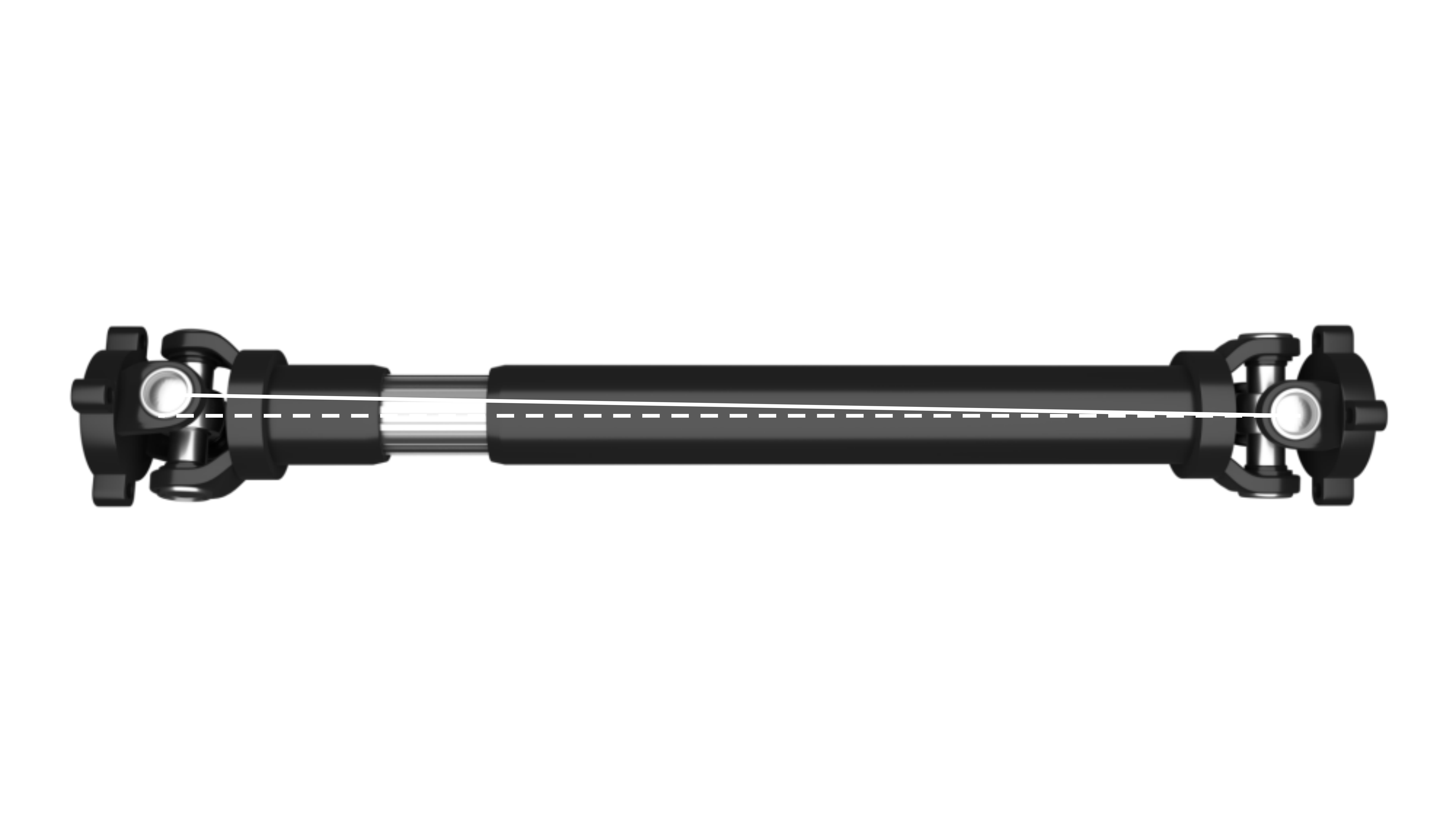
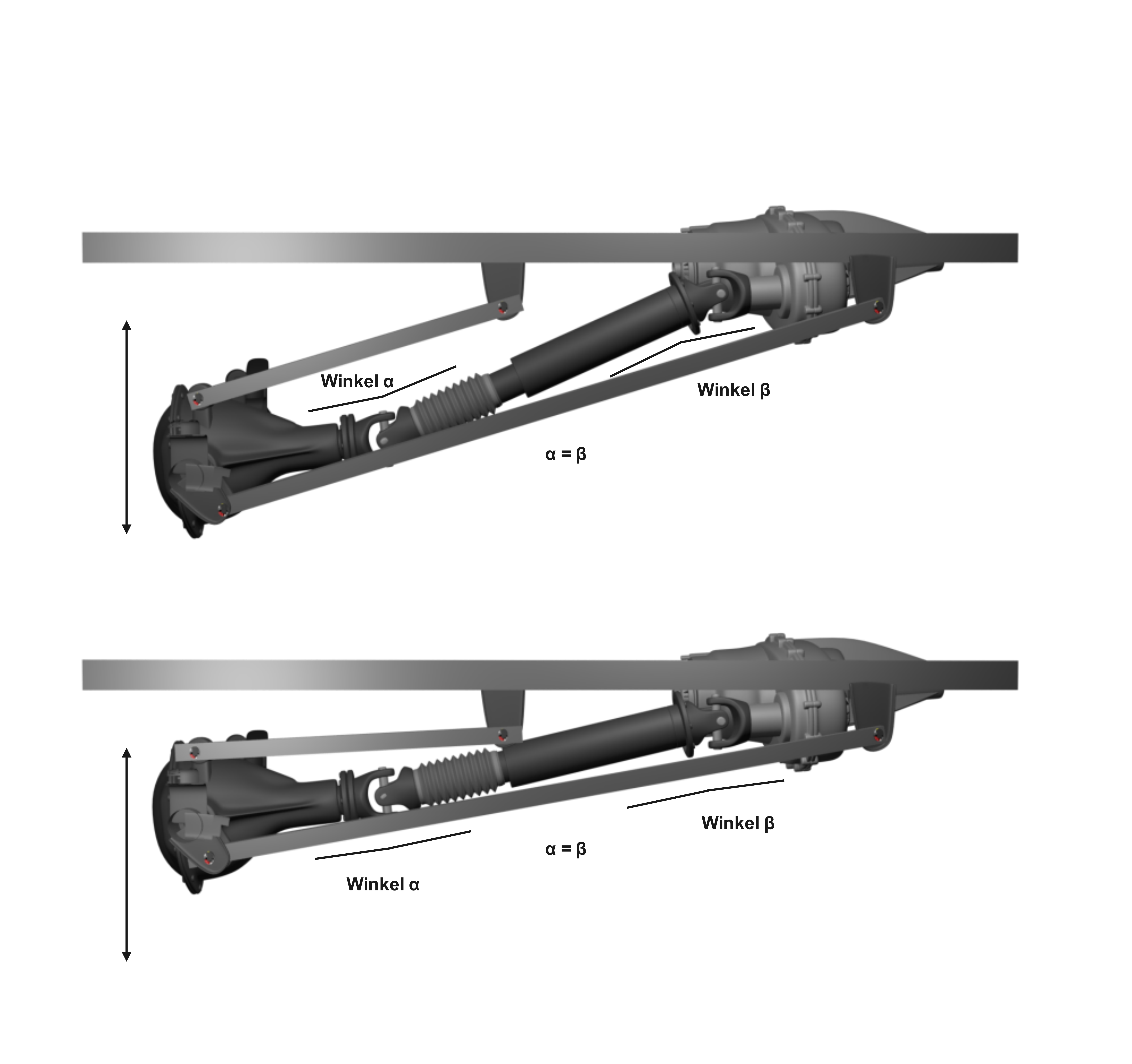
The Z-configuration is found in the drivetrain as a propshaft. Depending on the case, which we’ll come to, the W-configuration is integrated there. Usually the yokes are in phase. For the usual ride height, the input shaft and output shaft ideally lie parallel.
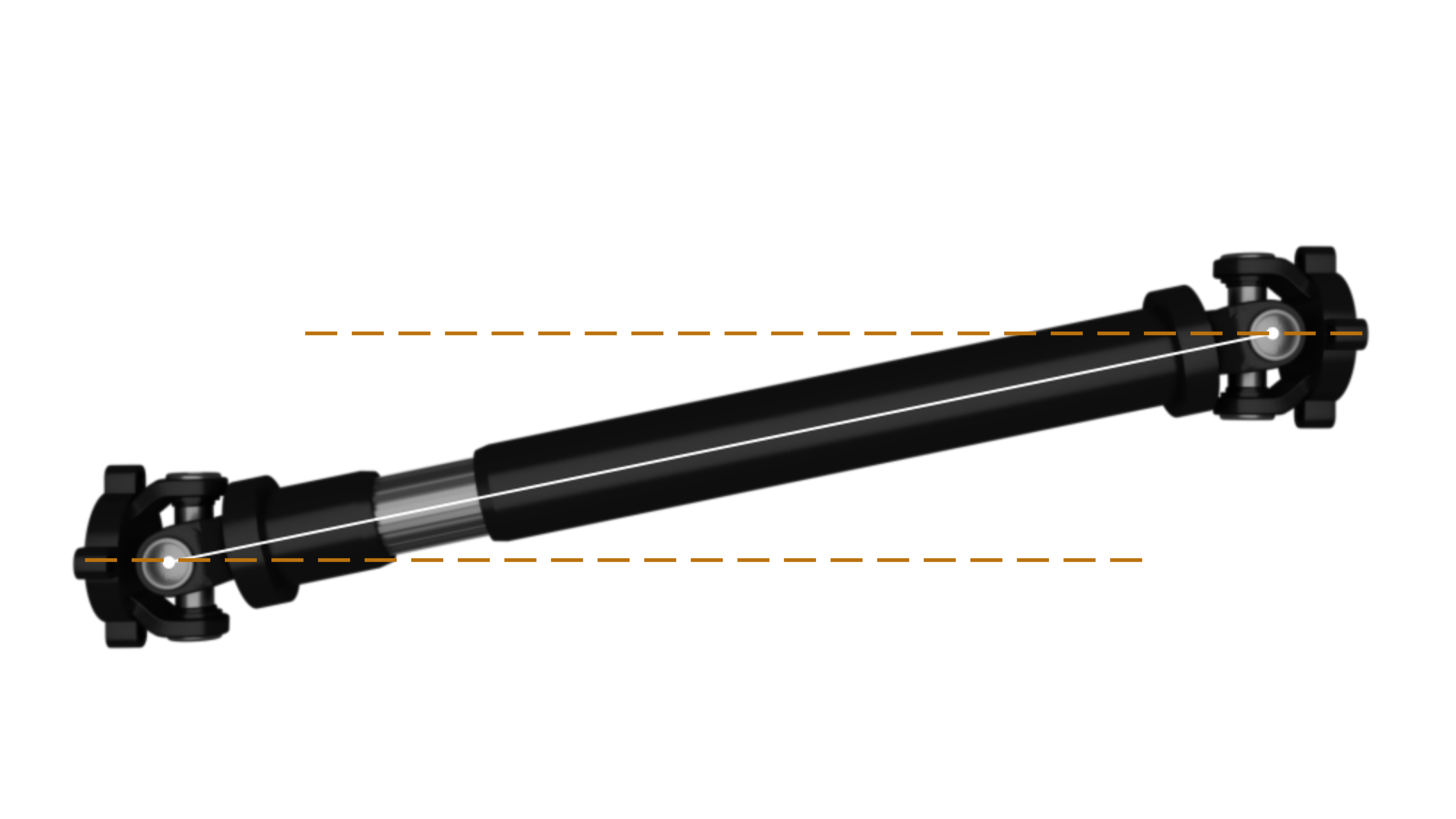
In the ideal case the Z-configuration also meets a further condition for even running: the two working angles lie on one plane.
W-configuration
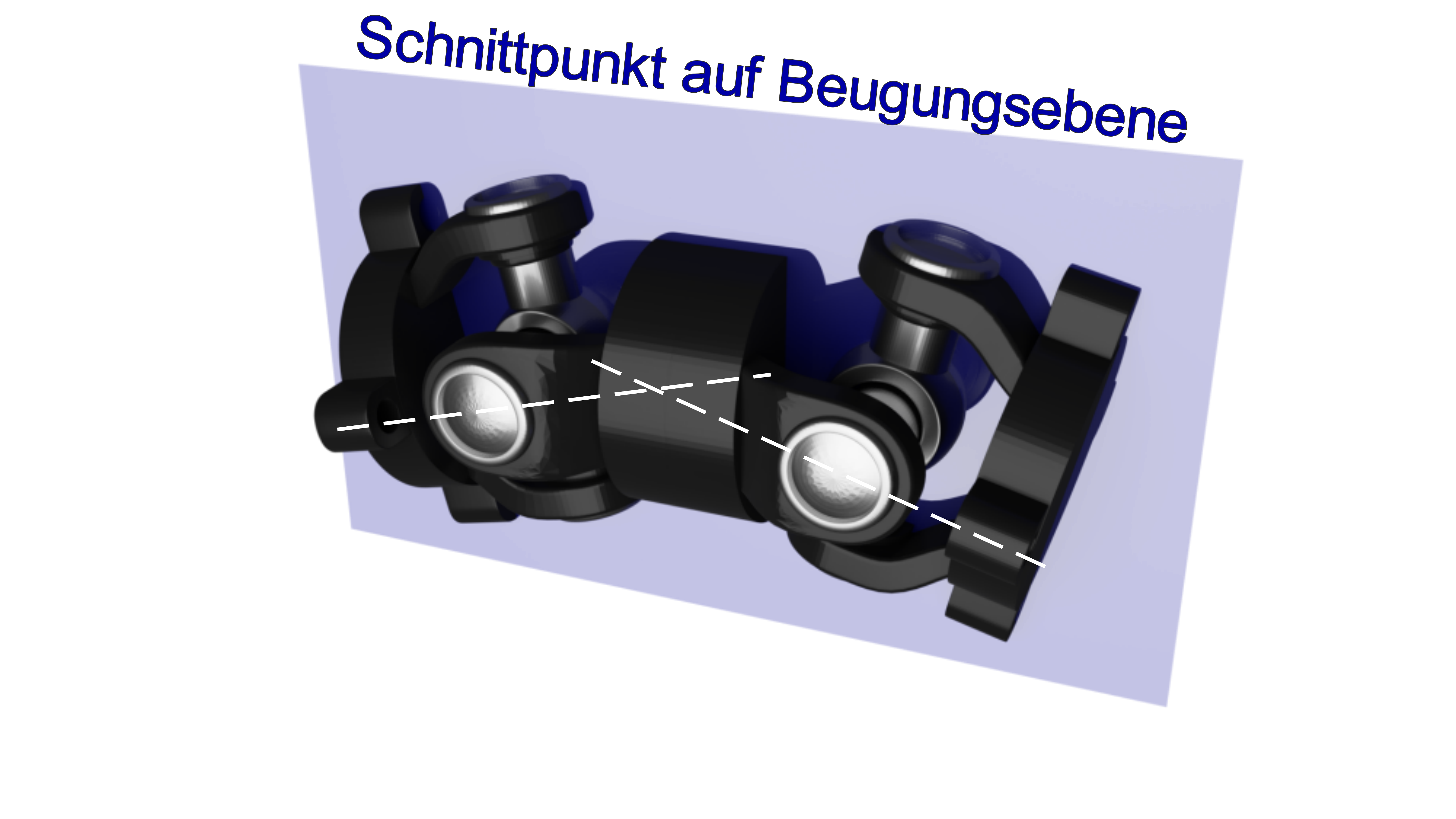
The W-configuration is usually found as a double Cardan joint either, on certain vehicle configurations, at one end of the propshaft, or as a steered drive shaft at the front axle. There are three kinds of double Cardan joint, with vehicle steering mostly using double Cardan joints with external centring, which don’t offer true even running. Only double Cardan joints with a built-in guide device manage that.
Here too there’s a bend plane.
Shifted phase
Anyone who now looks at their vehicle from below may notice that some things said here seemingly don’t apply there. There are numerous examples on the market, e.g. the Land Rover Defender Td4 110, Range Rover P38 or the 80 series of the Toyota Land Cruiser. Welcome to reality, which often demands compromises. But there’s an explanation for that too, and then it becomes clear that it’s only about meeting the conditions above as well as possible.
Normally a lot of value is placed on keeping the rear shaft vibration-free, as it’s much longer than the front one and so vibration is more likely to occur. We’ve already written something on that: the rotational error can be eliminated, the oscillation of the shaft can’t.
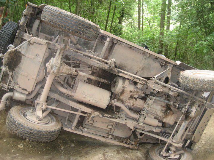
On vehicles like pick-ups, for example, that don’t have permanent four-wheel drive, it’s also the mainly driven shaft. So you find designs where the rear output shaft of the transfer case is tilted down to be as parallel as possible, or in line with, the input shaft of the differential, to keep the working angle as small as possible. That means both the engine and all flanged-on gearboxes lie slightly at an angle lengthways in the car. The positive result is that the shaft barely oscillates.
On the other hand it leads to a problem at the front axle, because there the output shaft then points up at an angle. Just like the input shaft of the differential. There’s no parallelism. There’s also often a sideways offset between the gearbox outputs and the differential inputs. With the shorter front propshaft, larger working angles then occur. There’s no longer a common plane either.

So what now? The magic word here is offset angle. Via a formula, with unequal angles and sideways offset on the shafts, an offset of the yokes can be calculated that leads to compensation again. They’re seemingly not in phase, but the offset serves exactly to reach this phase again, even if it doesn’t look like it.
So at the front propshaft in particular, an arrangement is found on vehicles that seemingly isn’t in phase. But that’s intentional.
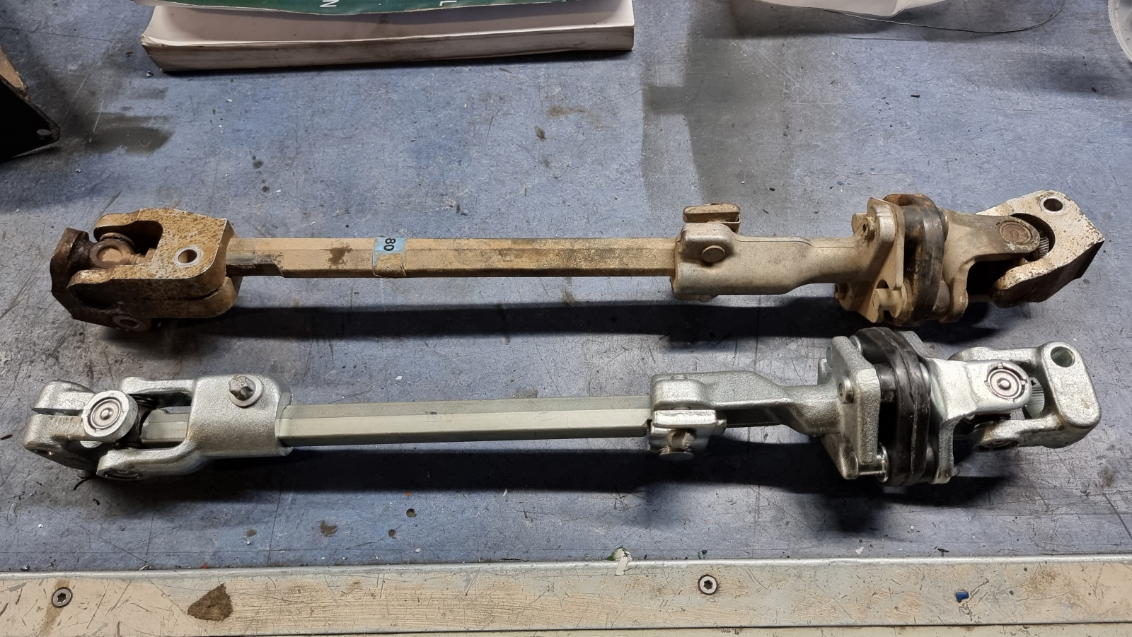
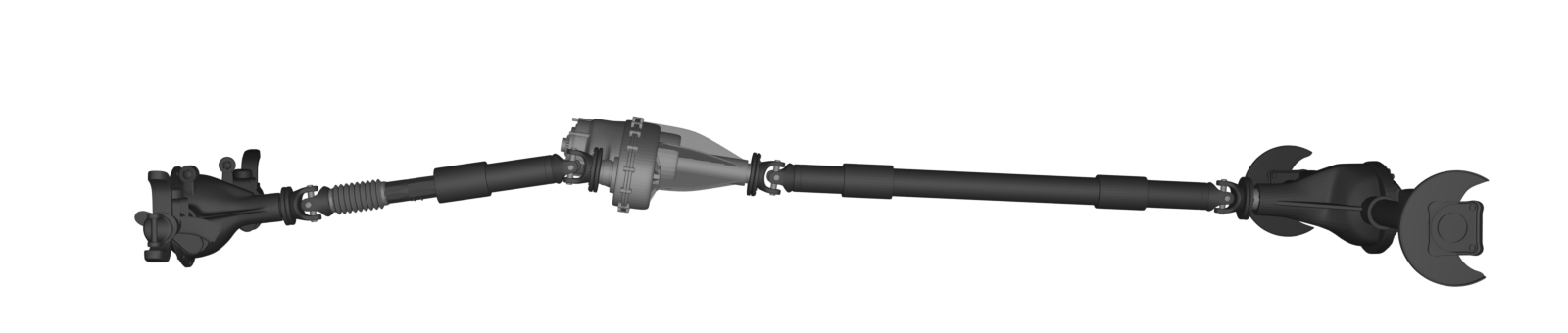
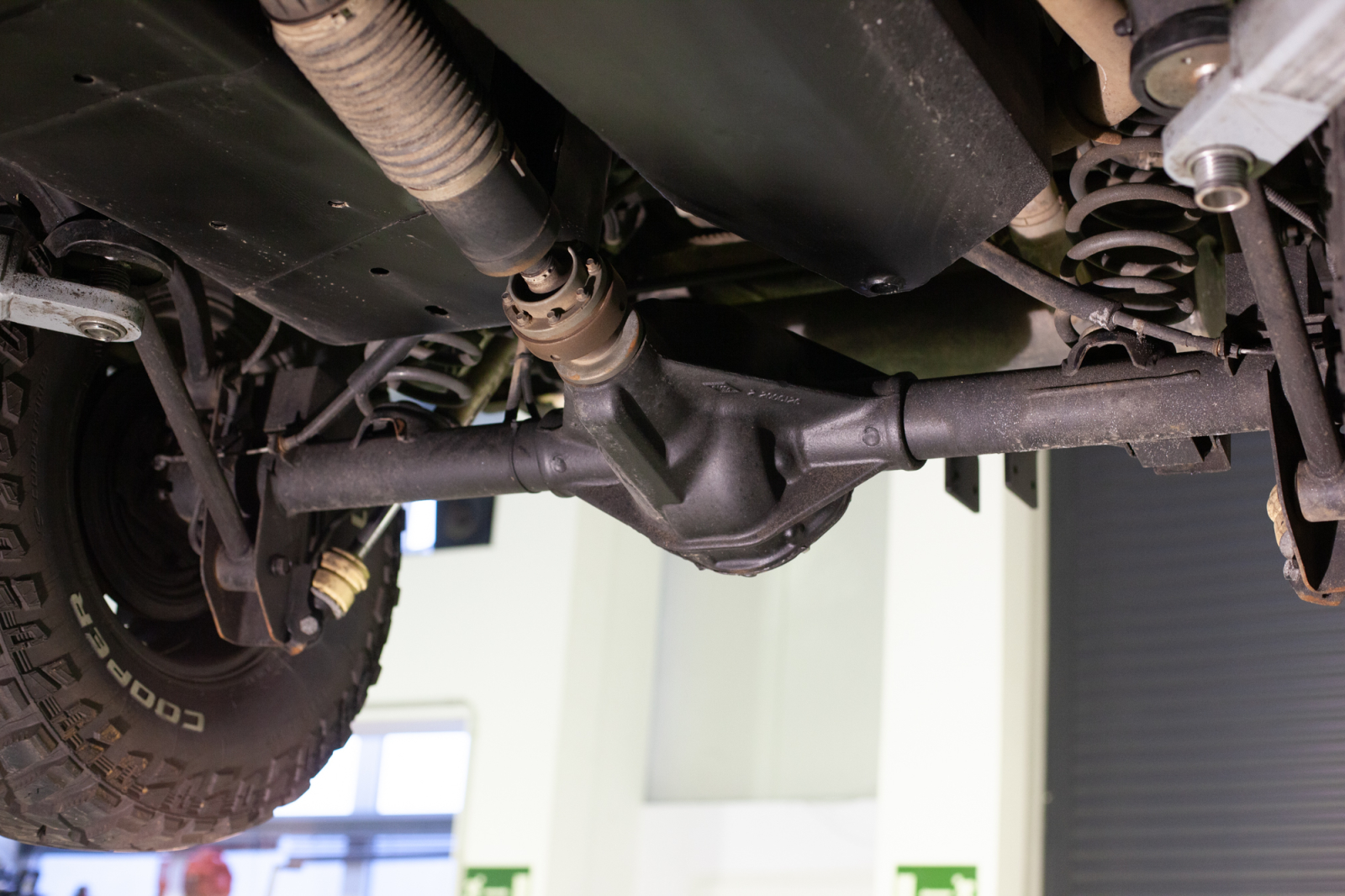
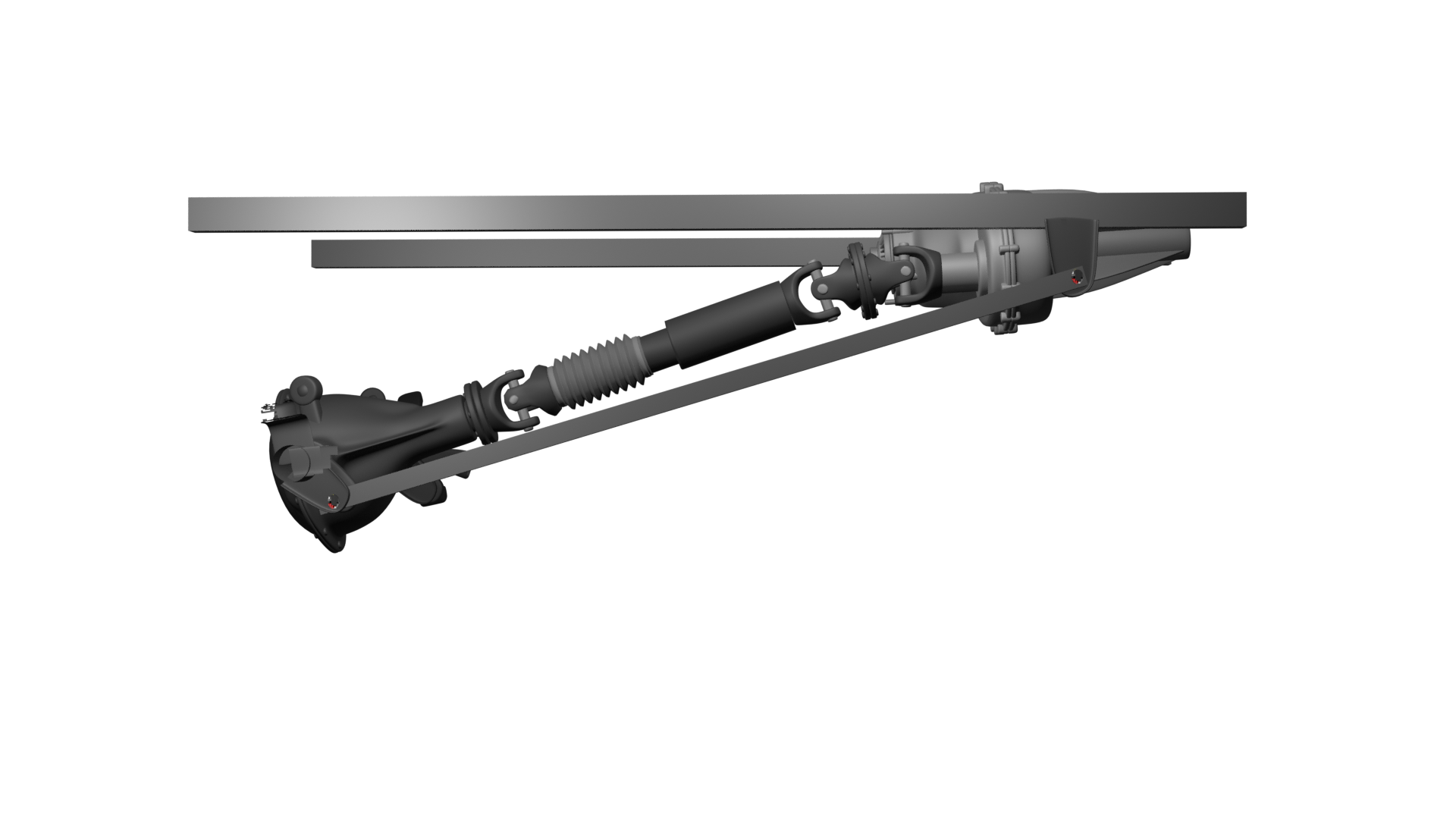
This image shows the propshafts of a 1986 Range Rover Classic Vogue. You can clearly see that an offset angle exists only on the front, shorter shaft. Look at the not-equally-aligned yokes of the shaft. Below it is the longer, rear propshaft, whose yokes sit the same and are in phase.
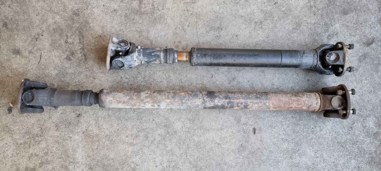
Upper front propshaft: with offset angle.
Lower rear propshaft: without offset angle (in phase)
The double Cardan joint, often misunderstood
If vibration occurs in the vehicle after a lift, people often reach for the double Cardan joint. But how come it sometimes actually helps and sometimes doesn’t?
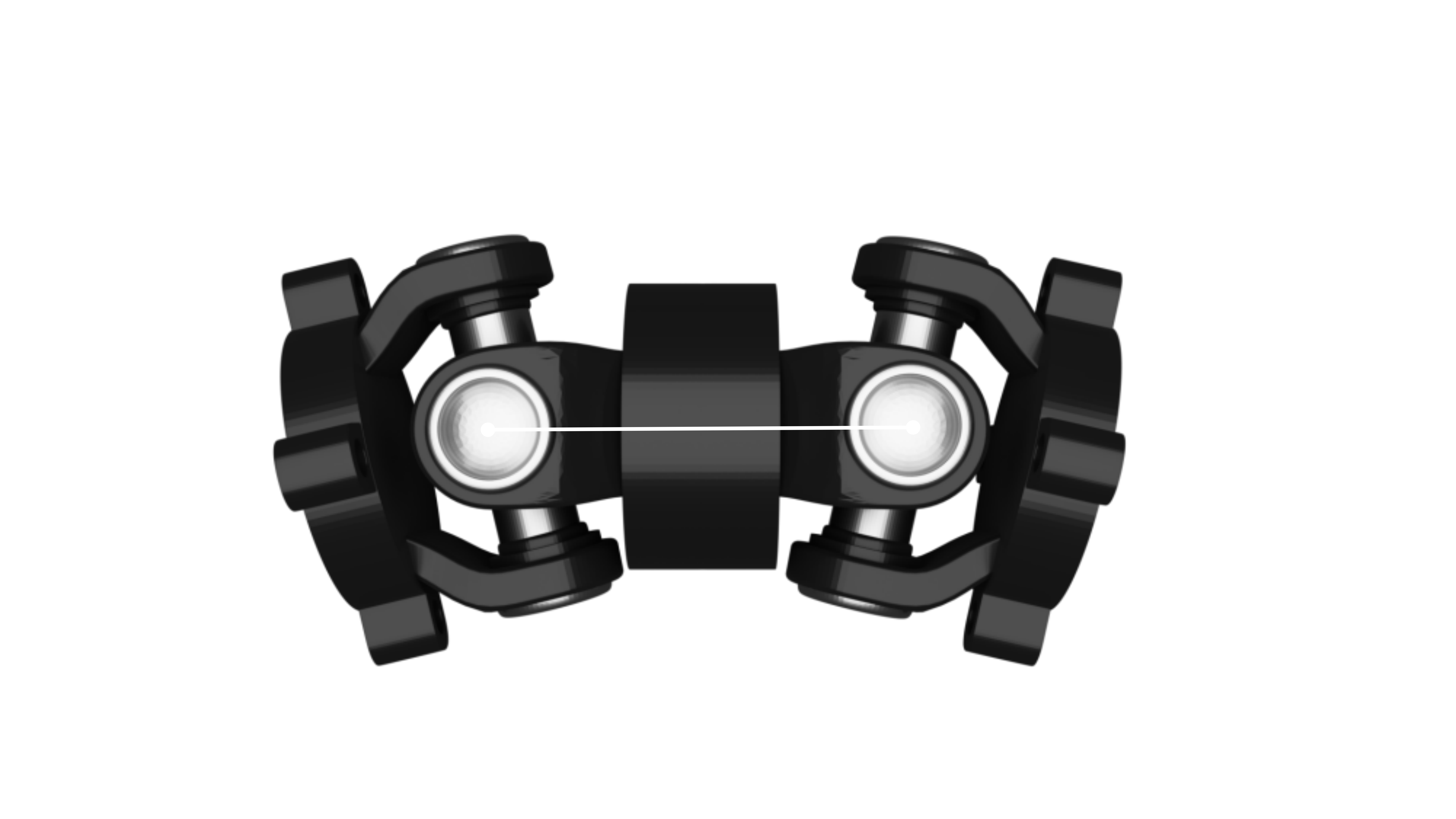
First of all, what even is a double Cardan joint? If you look at a double Cardan joint, it’s easy to see that it’s nothing other than a very short, compact propshaft with a universal joint at each end. And that has a meaning that’s often overlooked.
Let’s look at the conditions described once more closely and apply them to the double Cardan joint. One condition says that to balance out uneven rotation, a pair of cross joints is always needed. The double Cardan joint is such a pair, and that leads to an important realisation: the double Cardan joint brings its own uneven running into the rotation via its first joint and eliminates it through its second joint. From that it follows: a double Cardan joint cannot compensate the rotational error of other universal joints! It’s a self-contained system that only corrects its own error.
So what’s the point of using such a joint? That brings us to the next condition: input and output shaft have to stand parallel to each other so the joints stand at the same angle. Let’s look at the various axle locations for that. There are four-link axle locations that make sure the axle doesn’t twist on compression and rebound and so the angle of the input shaft into the differential stays unchanged too. So it’s guaranteed at all times that the Cardan angles at the gearbox output and the differential input are the same. If one of the universal joints is replaced by a double Cardan joint, it only brings an error into the system, as the number of universal joints is now odd.
If it’s an axle location with two trailing arms, the axle turns with the differential on compression and rebound, on the radius the trailing arms move on. The result is that the universal joint at the differential barely angles and stays nearly straight. The universal joint at the gearbox, on the other hand, is angled differently.
So the condition that the shafts should lie as parallel as possible isn’t met and vibration arises. Here the double Cardan joint can actually take vibration out, even though the number of universal joints is uneven. Why? Because the universal joint at the differential halves the working angle, stands nearly straight and so produces almost no rotational error.
The conclusion is, it depends on the axle location and on the time a vehicle stays at one height. For off-road vehicles that means: 4x4s have a standard height they’re at most of the time. The system is designed for this height. Brief changes within the intended range have no noticeable effect.
If this height is left permanently, it depends on whether the angles of the input and output shaft stay parallel or not. If yes, no double Cardan joint should be used. If no, it can help should vibration occur from the permanently sharpened angle.
Double Cardan joint in the steering
The double Cardan joint is often found at the steered front wheels. Even if they don’t reach the quality of CV joints, they are a good alternative. The task is to transmit a rotation over an angle in a small space. With just one universal joint, according to the conditions named above, uneven running would arise at once. By balancing out its own rotational error in the smallest space, the double Cardan joint is well suited to steered front wheels.
Distinction from the CV joint
A suitably designed universal joint, or better a combination of two universal joints, can run without Cardan error. This is where the distinction from CV joints lies. Unlike the universal joints, only one CV joint is needed to achieve even running, and that across all arrangements of the shafts to each other. They’re also able to transmit higher speeds and torques over larger working angles.
You’ll find the CV joint not only at the steered wheels, but on some vehicles at the propshafts too.
A double Cardan joint is not a CV joint
A double Cardan joint is happily called a CV joint too. But it isn’t, it only behaves that way under certain circumstances. A CV joint consists of a joint that produces no error in the first place.
Influence of the axle location on the universal joints
Four-link and parallelism
The four-link axle location is found on very many vehicles at the rear axle. At the front axle it’s found more rarely, as it has no self-stabilisation and takes a certain amount of space. I know of only two vehicles that currently have a four-link front axle, and those are the Jeep Wrangler and the Ineos Grenadier.
Depending on the arrangement, the axle there doesn’t turn with on compression and rebound. So the output shaft from the transfer case and the input shaft in the differential stay nearly parallel too.
Axle without four-link
Without four-link axle location you see that the axle turns on compression and rebound. Depending on where the trailing arms are fixed to the vehicle frame, the angle of the propshaft at the differential barely changes as a result. In relation to the conditions named, here we only have one angle that changes noticeably. Within a certain range that’s no problem. With a permanent lift, though, you may reach the limits.
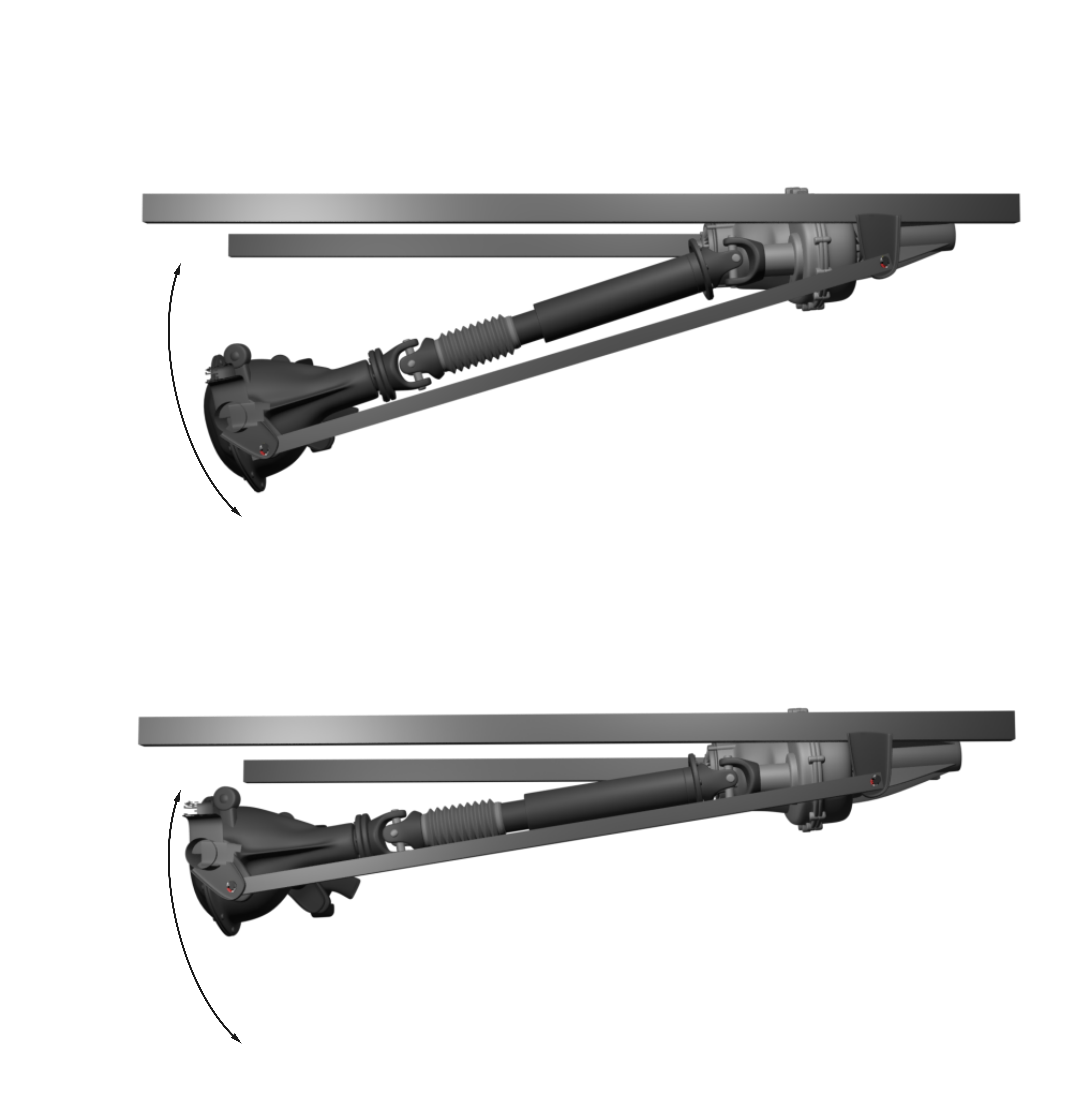
After a lift and with the axle far rebounded, the double Cardan joint can then help, as it halves the bend angle at the transfer case by splitting it across its two joints. It does eliminate its own error, so only a flat angle is left and the error stays in the uncritical range.
Maintenance
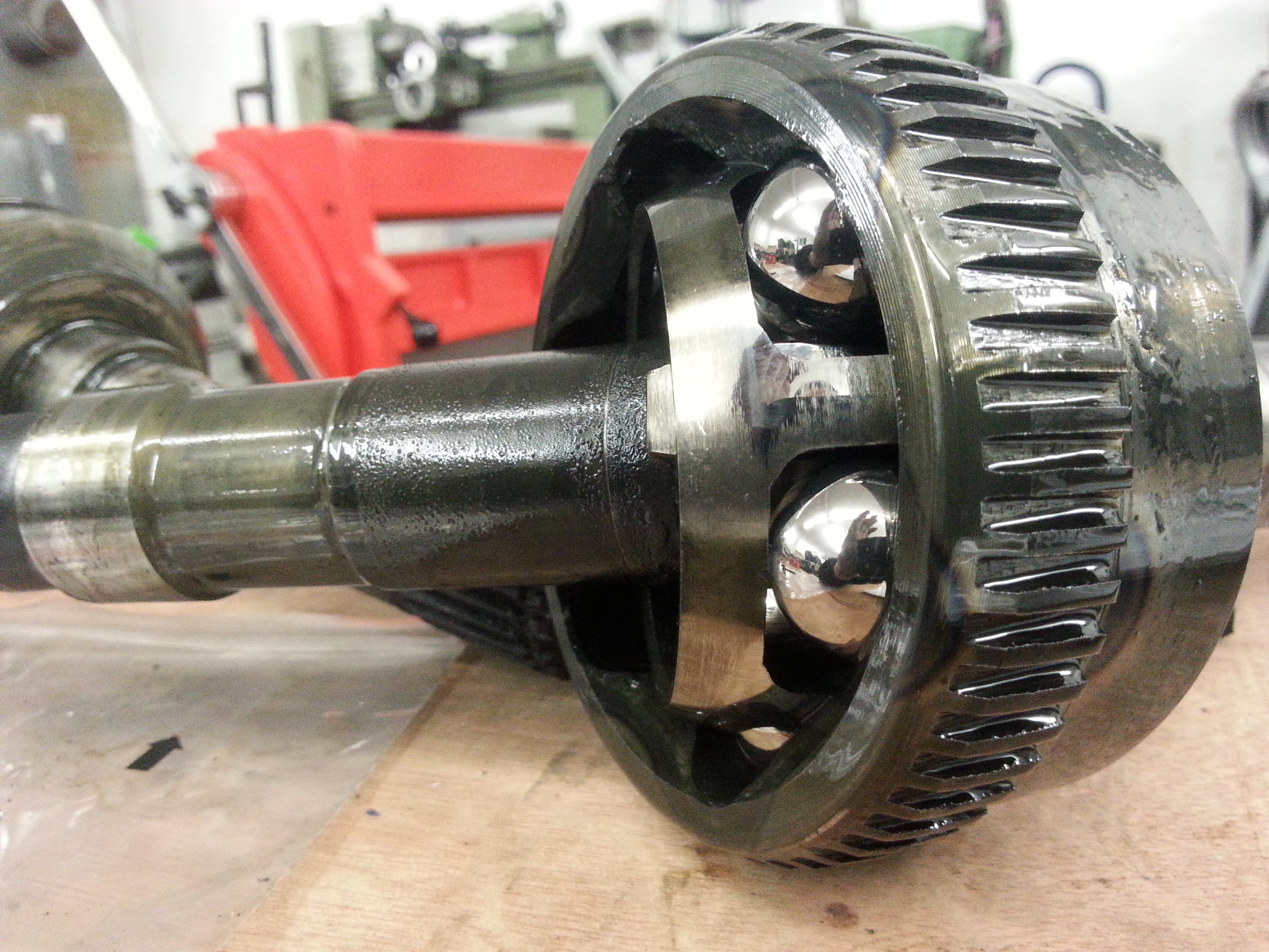
If your universal joints can be greased, you should do that regularly. Re-greasing is important, because it not only supplies the fine needle bearings with new grease, it also pushes out residue, debris and dirt. The seals are specially designed to let grease, and so unwanted contamination, out.
Make sure the new grease really comes out of all four cups. The bearing caps are designed so the grease reaches the needle bearings. The grease of course takes the path of least resistance, so bearings could be left unsupplied. If that happens with the shaft fitted, turn it and try again. If it still doesn’t work, you have to remove the shaft so the joint is completely unloaded. If it still doesn’t work then, damage may already have occurred, then you have to take it apart.
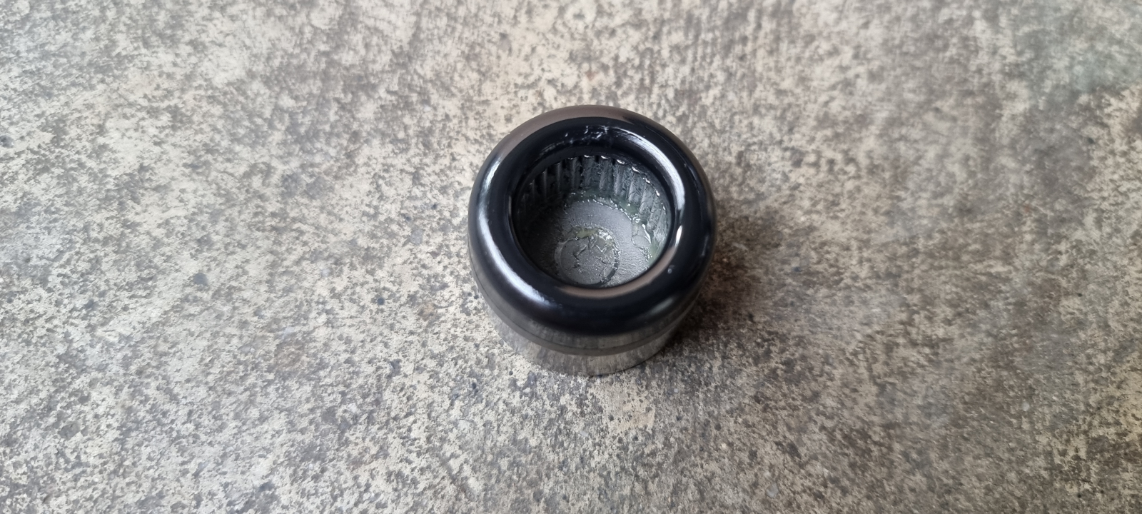
Here you see the needle bearing in the bearing cup with the small recess in the cap that lets the grease past.
When you remove the propshaft, make it a habit to mark the position of the shaft end to end. Either with a centre punch or a pen that can also write on oil, grease and dirt. There’s such a thing in car accessories and it’s helpful in many places, for example the Edding 8750. Put a mark each at the differential flange and the universal joint, on the shaft and slip yoke, and on the universal joint and flange at the gearbox.
For road use it’s enough to re-grease at every engine oil change. If you’ve been off-road, especially after mud and water crossings, you should re-grease at once.
Tools
It doesn’t take much to service a propshaft. In any case a one-handed grease gun is recommended. Often the coupler tilts or jumps off the grease nipple. There you need a free hand to hold the coupler. With the other hand you can then pump the grease.
We’ve worked for many years with the BGS 3140 grease gun with the extension hose. The usual 400g grease cartridge fits in it. Which grease is the right one, please take from your vehicle’s service figures. Mostly it’s a lithium-soap grease, like the 3552 from Liqui Moly. It has to be able to take high pressures, prevent water getting in and it has to protect against corrosion.
Usually there are up to three grease points on a propshaft. One each at every universal joint and one for the slip yoke of the shaft, which allows the length compensation of the shaft on compression and rebound.
The coupler of the grease gun has to click onto the grease nipple with light pressure and sit straight to it, so the openings of coupler and grease nipple line up. Otherwise you only press the grease past the side of the grease nipple. Always have a paper towel or rag with you to wipe everything clean again after greasing. If you find dark, greasy spots on the underbody or frame in the area of the universal joint, those can be grease residue flung off while driving. No cause for concern.
Replacement grease nipples and other aids
Normally the grease nipples come with the universal joints. You then screw these into the joint yourself. If you notice you can’t reach the grease nipple well with your grease gun’s coupler, you can buy other, e.g. longer grease nipples in the accessory range. You just have to see which shape is suitable and which thread is specified. There are also extra-narrow couplers and ones with a joint that don’t turn with and off when manoeuvring under the car.
Spotting a faulty universal joint
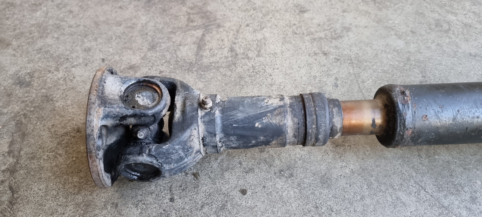
Part of the regular check, especially before longer trips, is to check the play in the universal joint. That’s quick and easy to do. You grip the shaft and the universal joint at the flange firmly and try to move both against each other. Up and down and sideways. There must not be the slightest play to see and feel. If there’s play, a replacement is due.
In this video a lot of play is already visible. Far too much, there should be none at all.
If you notice a knock or a jolt while driving on the throttle on/off, that can have many causes. One possible cause is such play in the universal joint. Then too a check of the joints is worth it.
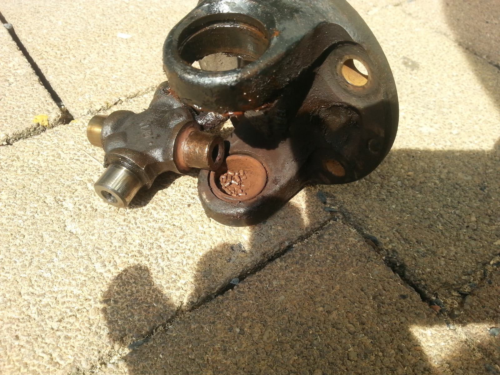
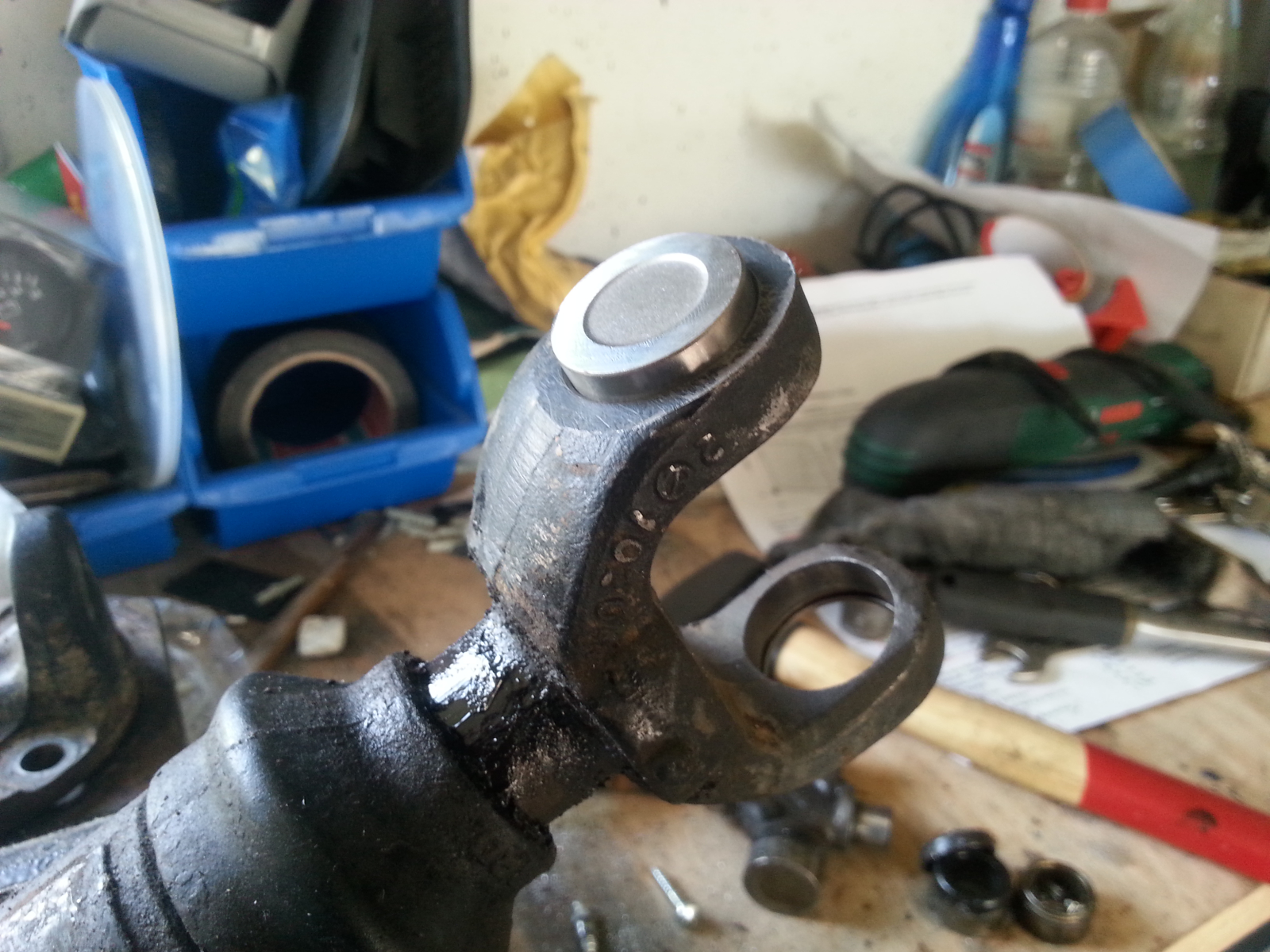
If you find on replacement that the bearing caps no longer hold in the bores of the yoke or even fall through, the flange or the shaft, depending on which side it concerns, is to be renewed.
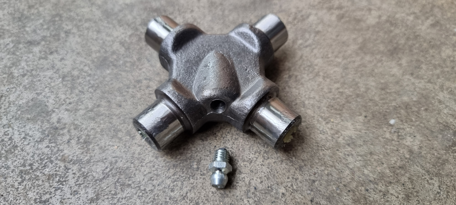
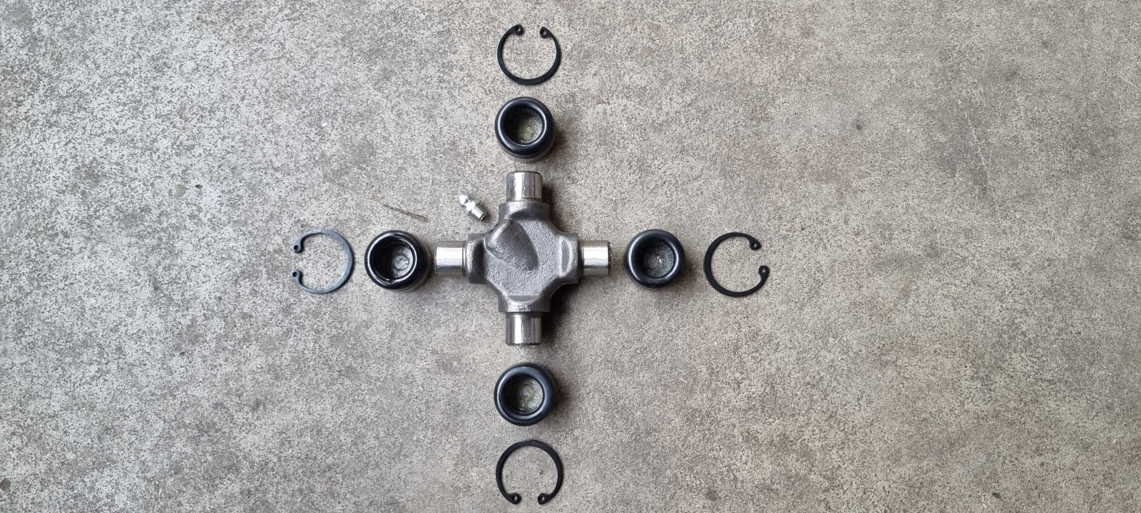
Usually you get the spider with the bearing caps, grease nipple and circlips as a replacement. When fitting, watch how the grease nipple will end up sitting if, as in this example, it’s screwed into the spider at an angle.
The whole thing as a video
Anyone who wants to know even more about universal joints, the theory behind them, maintenance and real implementations on the vehicle can watch our first Matsch&Piste Academy tech video.