Toe, camber and caster, most people will surely have heard these terms around wheel alignment. They have to be set correctly. But why exactly? Why do wheels stand neither straight nor vertical, and what is caster anyway? If you’ve ever wondered about that, then read this guide.
Anyone who’s already wondered why the front tyres have worn unevenly or the vehicle pulls to one side should have their wheel alignment checked and set. In normal driving, but also when things get rougher for the wheels and axles, the alignment parameters tend to shift. In addition, wear of rubber mounts and bushings can be responsible for the alignment parameters no longer being precisely maintained and the car feeling vague.
Changes to the wheel alignment alter important things that concern safety, comfort and handling. As a rule, anyone who wants to get the maximum out of their vehicle starts with the tyres first, then the right suspension setup, and last comes the power. Anyone who intervenes here without sufficient knowledge can make a lot of things worse. In the best case the comfort is gone and tyre wear is high, in the worst case the car becomes an unpredictable and uncontrollable skidder.
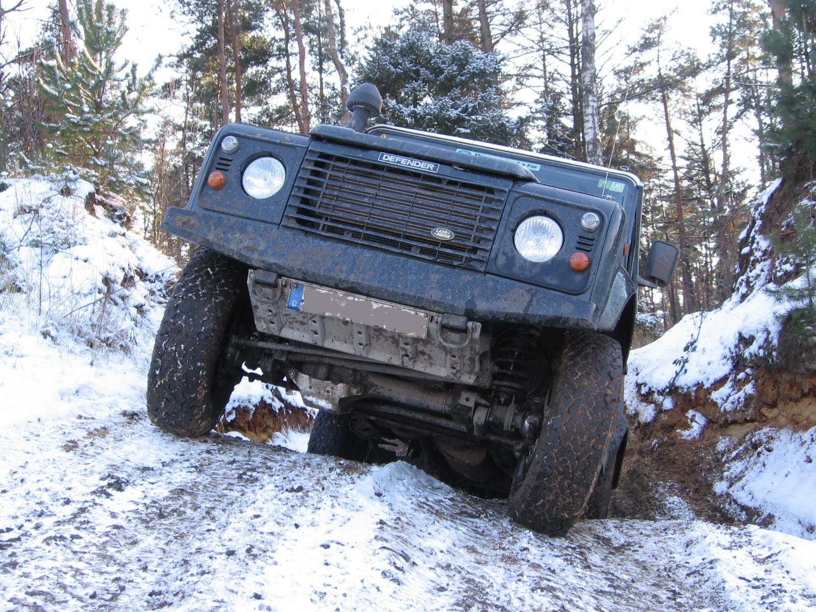
It’s good that drivers of an off-road vehicle with solid axles don’t have to deal with the full complexity and science around suspension settings. On the front axle there’s just one adjustable parameter, the toe. On the rear axle there’s none. There the wheels stand nicely straight. At the latest when lifting the vehicle, though, a few topics come up for solid-axle drivers too.
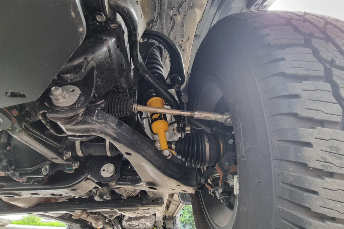
Drivers of off-road vehicles or pick-ups with independent suspension, mostly on the front axle, have to consider more, because the sometimes very elaborately constructed wheel suspensions with their numerous arms, rubber mounts and bushings are much more complex. Double-wishbone suspensions, which have an upper and a lower arm, are often used here. They dynamically change their parameters like camber and toe when cornering and so can be adapted to many uses, for example to always have the maximum contact patch or maximum grip.
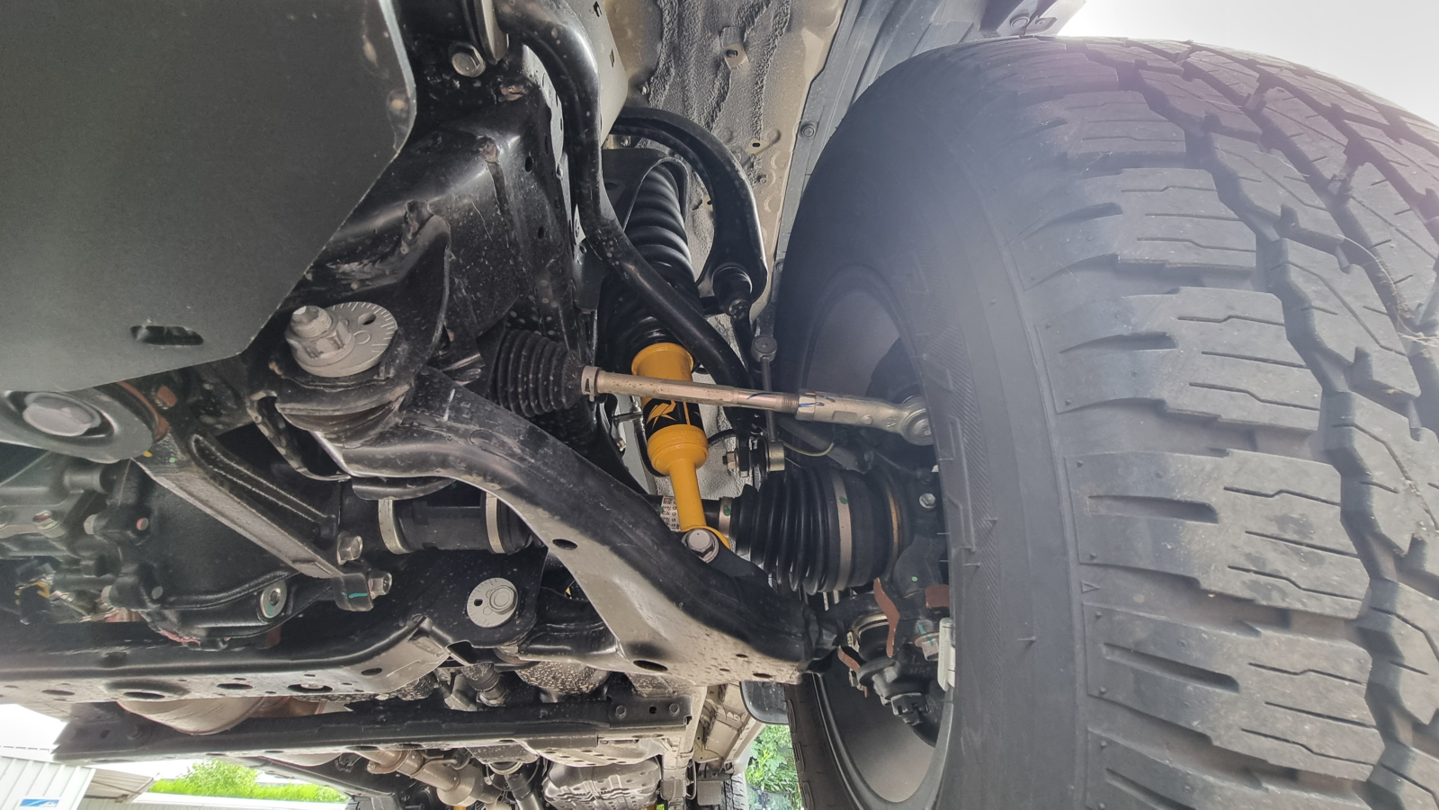
That’s why they also have better ride comfort and more safety, but on the other hand are more sensitive and more expensive to repair. Unlike with solid axles, more parameters have to be kept an eye on here: toe, camber and numerous bushings of the various arms.
Below we discuss the three essential parameters toe, camber and caster and explain what purpose they serve and how they take effect. Even though with solid axles only the toe can be set, on the front axle, the other properties are still present and, depending on the suspension conversion, have to be adjusted by swapping further suspension parts.
Tip: anyone who first wants to know what “arms” are should take a look here: Axle concepts in off-road vehicles – Part 2 – Trailing arms and Panhard rod on the rear axle.
Toe
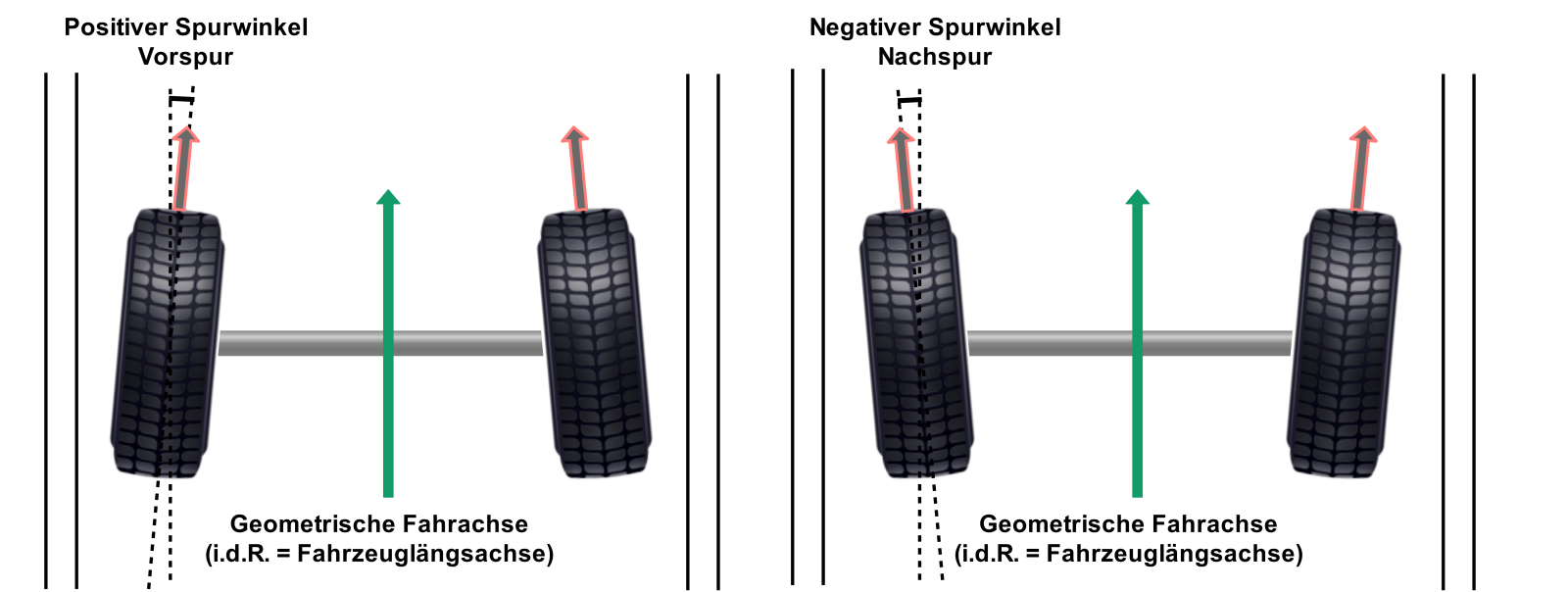
The toe indicates whether the two wheels of an axle point outwards or inwards in the longitudinal direction of the vehicle. You look, so to speak, down at the wheels from above and then they’re inclined either inwards or outwards. If they point outwards, that’s called toe out, if they point inwards, toe in. If they stand straight, that’s called zero toe. This concerns both the front wheels and the rear wheels.
With a solid rear axle there’s usually no toe adjustment, the wheels stand parallel to the longitudinal axis of the vehicle at zero toe. Otherwise the drive shaft and driver would jam against each other, or with a one-piece drive shaft the shaft would bend permanently. On the front axle that’s possible, because the drive shafts are interrupted by a joint that allows a different position of the wheels.
The amount of adjustment is given either as an angle in degrees and minutes from the longitudinal axis, or in millimetres by which the inner rim flanges stand closer together at the front or rear.
Now you might immediately wonder why? If the wheels don’t run straight and parallel to the longitudinal axis, then surely the tyres are constantly scrubbing across the ground! Yes, that’s right, but it’s intentional and it carries only low and acceptable wear, provided the permitted tolerances, which are tightly drawn, are observed. Common values are around 2.5 millimetres difference by which the rim flanges stand closer together.
What the toe does
With toe in, the wheels want to run towards each other, with toe out away from each other. So a permanent force arises that preloads the suspension. In the numerous rubber bushings and mounts the play disappears. As a result, the steering and the vehicle stabilise.
If the wheels stood exactly in the longitudinal direction, they could easily want to turn away now to the right, now to the left. The steering would flutter and an imprecise driving feel would arise. Through the preload, the driver is given a considerably better feel and feedback from the road. A small part of the restoring forces that turn the steering back to straight-ahead after turning in also arise from the toe.
Another effect is the preloading of the tyres’ tread blocks. As a result the tyres have better grip. For tyres there’s a measured curve that indicates what grip they have at what amount of twist from zero toe (see How tyres work). In motorsport, the tyres are even twisted during cornering to such an extent that high wear arises, but it’s rewarded with maximum grip (see Ackermann condition).
The total toe
The total toe is the sum of the toe on the left and right. With vehicles with independent suspension and toe adjustment on both sides, this can differ. In total it should of course be 0, since on one side there’s a negative value and on the other the same positive value. But even if the total toe isn’t 0, the vehicle drives straight ahead, because the wheels align automatically through the acting forces so that the same forces act on both sides. The result is a crooked steering wheel.
With vehicles with a solid axle, an adjusted toe has no effect on the position of the steering wheel. The steering wheel can, however, stand crooked if the drag link isn’t set correctly.
Starting point of the measurement
Now it does get a bit more complicated. Above we wrote that the toe, at least on the front axle, is measured relative to the longitudinal axis of the vehicle. But that’s not quite right, even if in practice it makes no difference in most cases. Because there’s a second axis that ideally lies on the longitudinal axis: the geometric thrust axis. And it’s determined by the rear wheels. If the rear wheels, or rather the rear axle, stand straight, the longitudinal axis and geometric thrust axis are the same, so no problem. If the rear wheels stand at an angle to the vehicle’s longitudinal axis, however, the geometric thrust axis lies at an angle too.
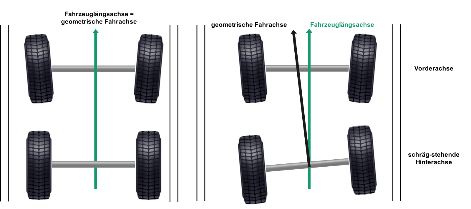
The wheels align themselves to the forces again into straight-ahead running in that case, but the whole vehicle stands crooked and drives along the geometric thrust axis.
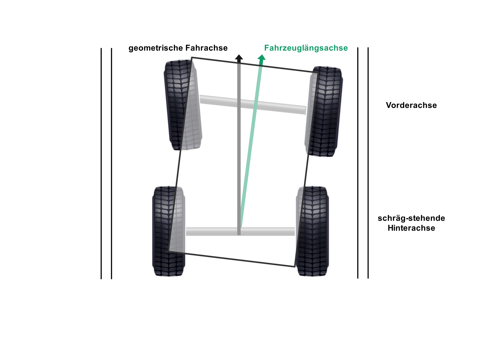
One case in which the rear wheels can stand permanently crooked is, for example, when one of the rear trailing arms is bent. Then the wheel on its side stands a bit further forward. The rear axle is then turned slightly out of the centre of the vehicle’s longitudinal axis. Another case would be an articulated rear axle, but that should only occur off-road and so has no noticeable effects.
A pronounced crookedness can have effects on electronic assistance systems. Forward-facing sensors, for example distance warners, then “look” slightly at an angle and possibly past the obstacle ahead.
Handling in relation to the toe
As long as the car drives straight and the road is even, you only feel the toe through the stabilised steering and the straight-ahead running. If the road becomes uneven, steering corrections become necessary. That’s because the momentary grip of the individual wheels determines where the vehicle goes. The grip in turn depends on the load pressing on the wheel. On a very uneven road, load and contact pressure change constantly, and thus the grip too. All of that at short intervals. The car then rolls now to the left, now to the right, depending on which wheel is just running over an unevenness and so briefly experiences a higher load. You have to make small steering corrections constantly, but that’s normal.
With solid axles, the set toe value itself doesn’t change when the axle compresses and rebounds. But the inclination at which the wheels stand to the road does change. These changes take place within an acceptable range. Only with considerable permanent lifts can noticeable effects occur. Mostly the restoring force decreases and tyre wear increases.
With vehicles with independent suspension, it depends on the construction and the geometry of the wishbones whether the toe changes when compressing and rebounding. With every vehicle, however, the toe changes when steering, more on that in the topic of the Ackermann condition.
Cornering
For cornering, the toe plays an important role. It helps determine whether the vehicle over- or understeers and whether it’s keen to turn in, i.e. whether it turns in quickly and easily or not. Mostly with solid axles and less sporty cars, toe out is chosen on the front axle, since, as described below, it allows calm and controllable turning in.
During straight-ahead running, neither of the two front wheels dominates, since both have the same grip. Now you turn in. If the vehicle has toe out, the inner wheel now already pulls the car into the corner, while the outer wheel has perhaps just reached the straight-ahead position or is already pointing slightly into the corner. The vehicle willingly follows the steering input. The vehicle now briefly runs the cornering line you wanted, up to the point at which the weight begins to shift due to centrifugal force. Now the weight presses more on the outer wheels, especially on the front wheel. The pressure on the front wheel is also increased because, when turning in, the speed is often reduced too. The outer front wheel now has the best grip of all and now determines where to go. Since, due to the toe out, it points slightly outwards, i.e. out of the intended cornering line, the vehicle begins to understeer. You can notice this in that you, mostly subconsciously, have to add a little more steering input shortly after the first turn-in. That’s the moment at which the outer wheel begins mainly to determine the direction. After the correction, the outer front wheel points in the desired direction to drive through the corner.
When you reach the range in which no more load change occurs and you drive constantly through the corner, the axle with the better grip determines what happens next. As soon as you change the load again, the cards are reshuffled. If you accelerate and so push more weight onto the rear axle, that can lead to further understeer if the toe on the rear axle is 0. If you brake or slow down, more weight goes onto the front axle and the car tends to oversteer (after all, you corrected the steering at the corner entry in favour of oversteer).
It’s the reverse with toe in. Here the outer wheel points more sharply into the corner, which is why the turn-in process runs faster and sharper. In addition, the tyres build up grip even better through the greater twist. To counteract the oversteer, you then steer back a little, you “open up the steering”. In the constant range, the same conditions then apply again as with toe out.
That was a somewhat simplified description. Further factors also come into play, like the cornering forces each wheel applies. With all vehicles the same physical factors act, but these change less with vehicles with solid axles than with vehicles with several arms. More complex wheel suspensions dynamically change some alignment parameters when cornering, and that makes capturing it much more elaborate.

Oversteer and understeer
To put it in the words of rally world champion Walter Röhrl: “Oversteer is when the passenger is afraid. Understeer is when I’m afraid.”
It can of course also be put a bit more precisely, and it doesn’t necessarily need a passenger. Understeer and oversteer describe whether the vehicle tends to turn in easily and, when cornering, tends to drive the corner ever tighter (oversteer), or whether it turns in a bit more reluctantly and drives the corner rather wide (understeer).
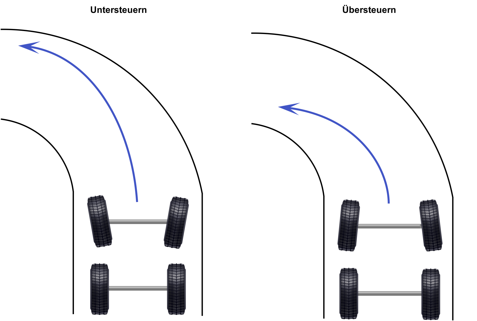
Depending on the vehicle type and character, one or the other is desired. In principle, front-wheel-drive vehicles tend to oversteer, since the outer front wheels pull the car into the corner. Rear-wheel-drive vehicles tend to understeer, since the rear axle pushes the car slightly over the front wheels to the outside of the corner.
Usually, oversteering vehicles are perceived as sporty. That’s probably why Walter Röhrl also prefers this behaviour, in which the car tends to “come round” with the rear, i.e. to break away at the rear. Röhrl then catches the rear again and drifts around the corner (though he’s not really known for putting the vehicle sideways, but for precisely driving the ideal line). Understeer is considered safer, but less sporty.
On the rear axle too there’s toe in or toe out, though with solid axles zero toe is found. With normal cars, toe in is always set, since it has a stabilising effect. Especially when cornering, the toe in works against the rear breaking away, since the outer wheel points into the inside of the corner with more grip. Toe out is only used by experts in motorsport, since the rear is steered outwards, which promotes the rear breaking away.
Mr Ackermann and his condition
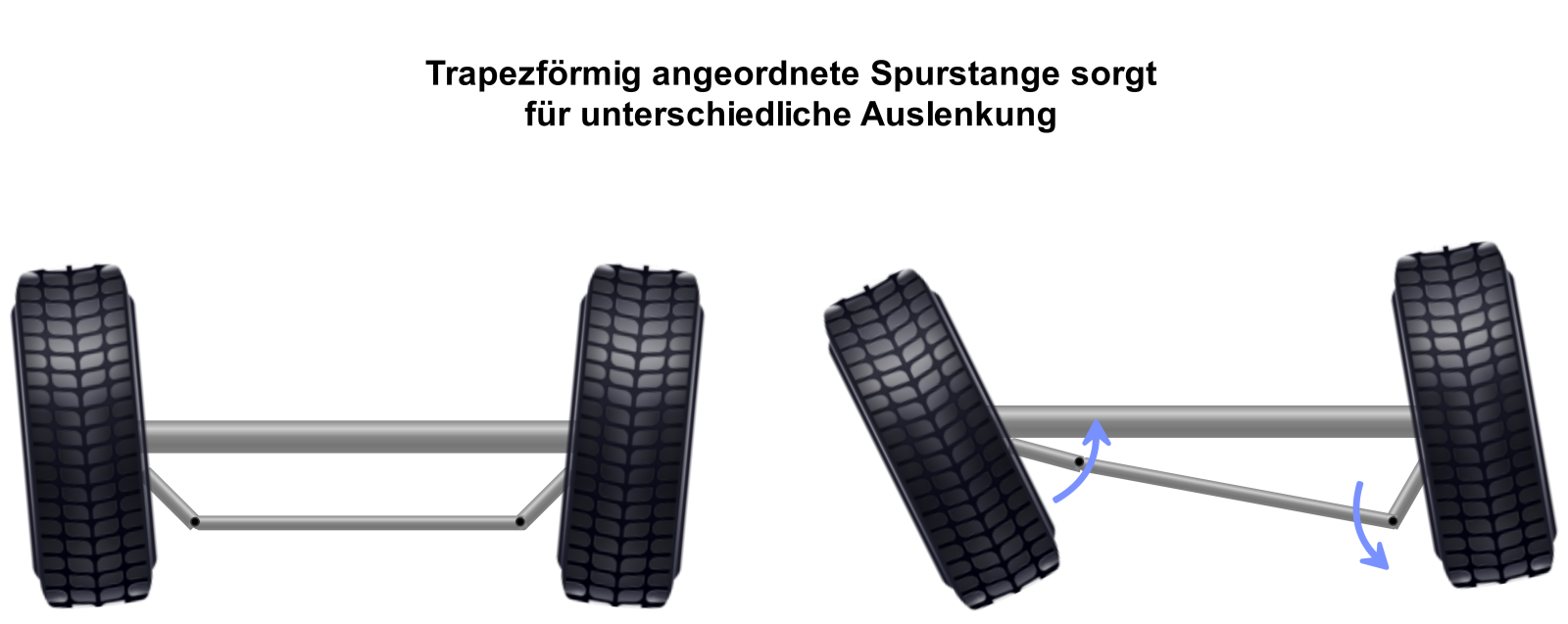
Perhaps you noticed in the cornering picture above that the front wheels don’t turn in parallel, but the inner wheel turns in more than the outer one. That’s fully intentional and is achieved via the track rod. Together with the axle, it forms a trapezoid. When you turn the steering wheel, the steering rod pushes or pulls a wheel to the left or right so that it turns in. Via the track rod, this movement is transferred to the second front wheel. Since the levers to which the track rod is attached stand at an angle, a trapezoid arises and one side then turns out more than the other.
It’s not irrelevant whether the track rod lies in front of or behind the axle. In the picture, the track rod is behind the axle, which is why the arms on which the track rod ends sit point towards the vehicle centre. If the track rod lies in front of the axle, the arms with the track rod ends have to point towards the wheels.
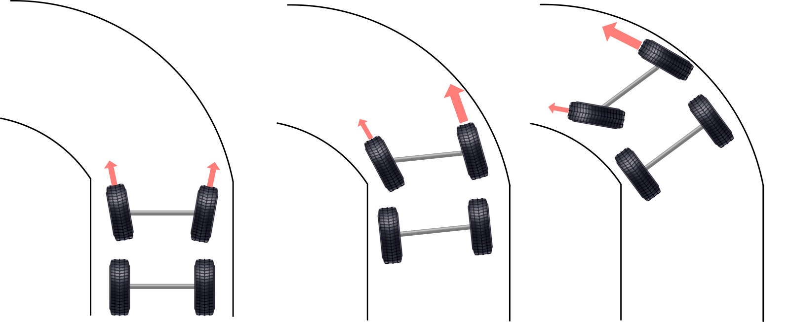
And why should that be the case? Because the good Mr Ackermann established, even before the invention of the automobile, that multi-track vehicles can only drive around a corner without scrubbing and problems if all wheel centres turn about one central point. Since two-axle vehicles have four tracks in the corner, something had to be devised. For the unsteered rear wheels that was still simple. They have the same turning centre, just a different distance to it. With the steered front wheels it’s different. If they turned in equally, they wouldn’t both meet the centre.
That’s why the inner wheel has to be turned in more. In the end, the extended centre lines of the wheels have to meet at this one pivot point so that the Ackermann condition is fulfilled. That’s the prerequisite for being able to drive corners without tyre scrub. So it spares the wallet and greatly increases ride comfort. If this is precisely observed, the design of the Ackermann angle is 100%. In the car sector, 0% to 50% deviation from the ideal angle is usual.
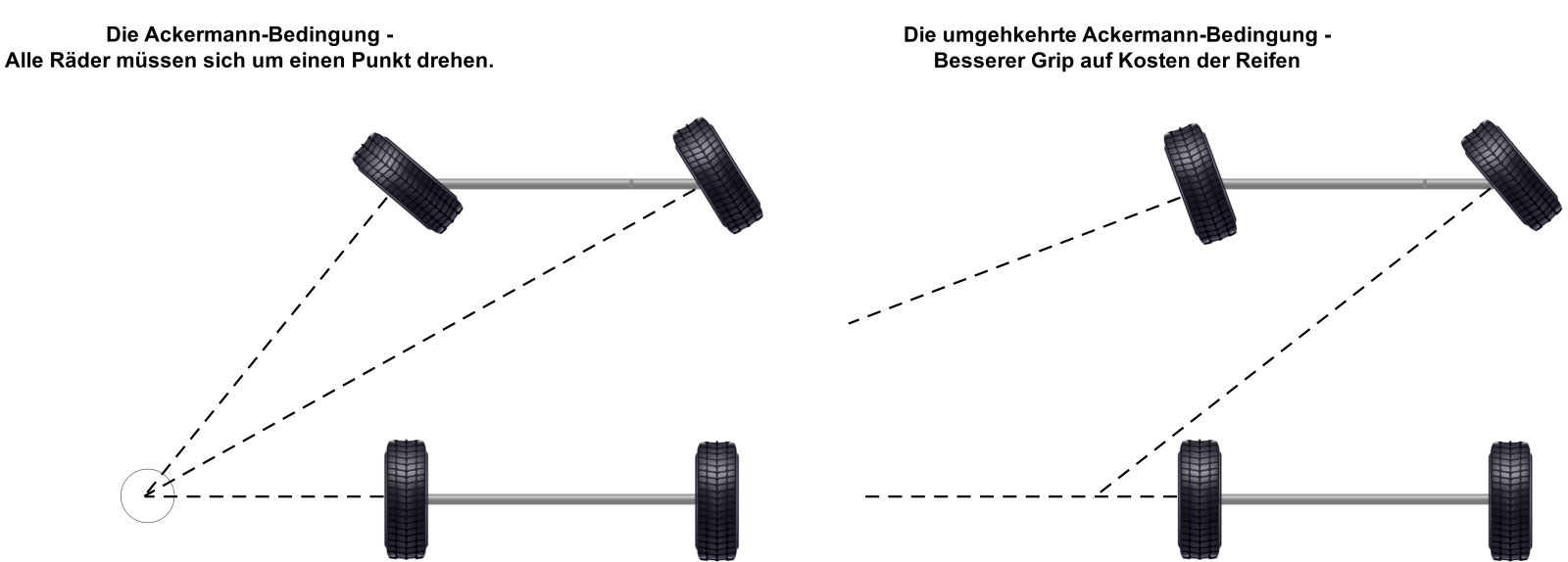
Anyone who now thought that’s complicated, I have to disappoint. Because the better grip comes with the at first counterintuitive parallel position of the front wheels to each other, or even a slightly reversed setting, which is why both are found in motorsport. In that case the extended axes no longer meet at one point, since the outer wheel stands parallel to the inner one or is even turned further into the corner than the inner one (anti-Ackermann).
The solution to the puzzle lies in the cornering forces a tyre can transfer to the ground. With real racing tyres these are very high when the contact patch is properly preloaded through the twist. The twist arises through the different alignment of the contact patch to the rim. Since the outer wheels, especially the front one, have to transfer most of the cornering forces, one rather forgoes the help of the inner wheels and uses the high capacity at the outer wheel. The price for that is higher tyre wear.
More on that in our article on tyre grip: How tyres work.
Camber
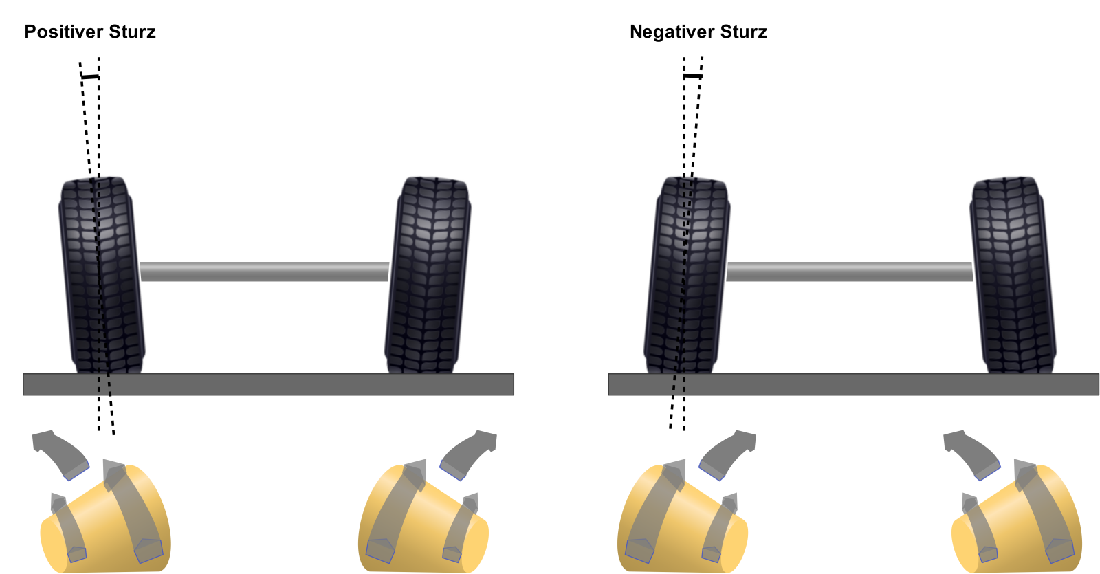
But we’re not done with the toe as far as the tyres are concerned. They’re not only set at an angle in the direction of travel, they’re additionally tilted in the vertical. That’s called camber. It’s positive when the top of the wheel is inclined outwards, and negative when it’s inclined inwards.
The effects that camber is meant to achieve are, on the one hand, again a stabilisation and, on the other hand, with negative camber, maintaining as large a tyre contact patch as possible when cornering. Through the tilting, the circumference of the tyre on the tilted side effectively becomes smaller. The tyre no longer has the shape of a cylinder but of a cone. Anyone who’s ever knocked over a drinking cup could observe the effect. The cup then rolls in a circle, with the side of the larger circumference going around the side of the smaller circumference. With the vehicle, the behaviour is then such that with positive camber the wheels want to run away from each other, with negative towards each other. Similar to the toe, a preload arises that way.
With all vehicles the effective camber changes constantly. Be it when steering or, with independent suspension, through the design of the arms. The changes happen partly through deformation of the tyres and are partly predetermined by the chosen geometry.
Handling
As with the toe too, the camber creates forces that stabilise the vehicle and the steering and eliminate play in the suspension parts. But the camber creates the biggest effect when cornering.
Cornering
When the car is in the corner, the outer tyres in particular curve in the lower area. As a result, especially the outer tyres, so important when cornering, lose contact area in the lower area. This effect is compensated by negative camber. With independent suspension, the arms can also be designed so that a different camber is created when cornering, for example in that the upper arm, when the vehicle leans into the corner, pulls the wheel towards it and so creates negative camber.
Off-road vehicles and commercial vehicles mostly have positive camber. This damps shocks to the steering better. Road vehicles, which normally also drive higher cornering speeds, mostly have negative camber, since, as already indicated, it increases the tyre contact patch of the outer wheels that are important when cornering. From that you can already tell that vehicles with a solid axle aren’t the best candidates for high-speed driving in the mountains, since they don’t have such a mechanism. They have no arms that adjust the camber when cornering.
Caster
If you see a shopping trolley, you can observe the effect of caster. The small castors don’t stand exactly under their pivot point but offset to it. That’s necessary so that they automatically align in the direction of travel and run along stably. Granted, with the shopping trolleys I get, that mostly doesn’t work, but that doesn’t change anything fundamental about this principle.
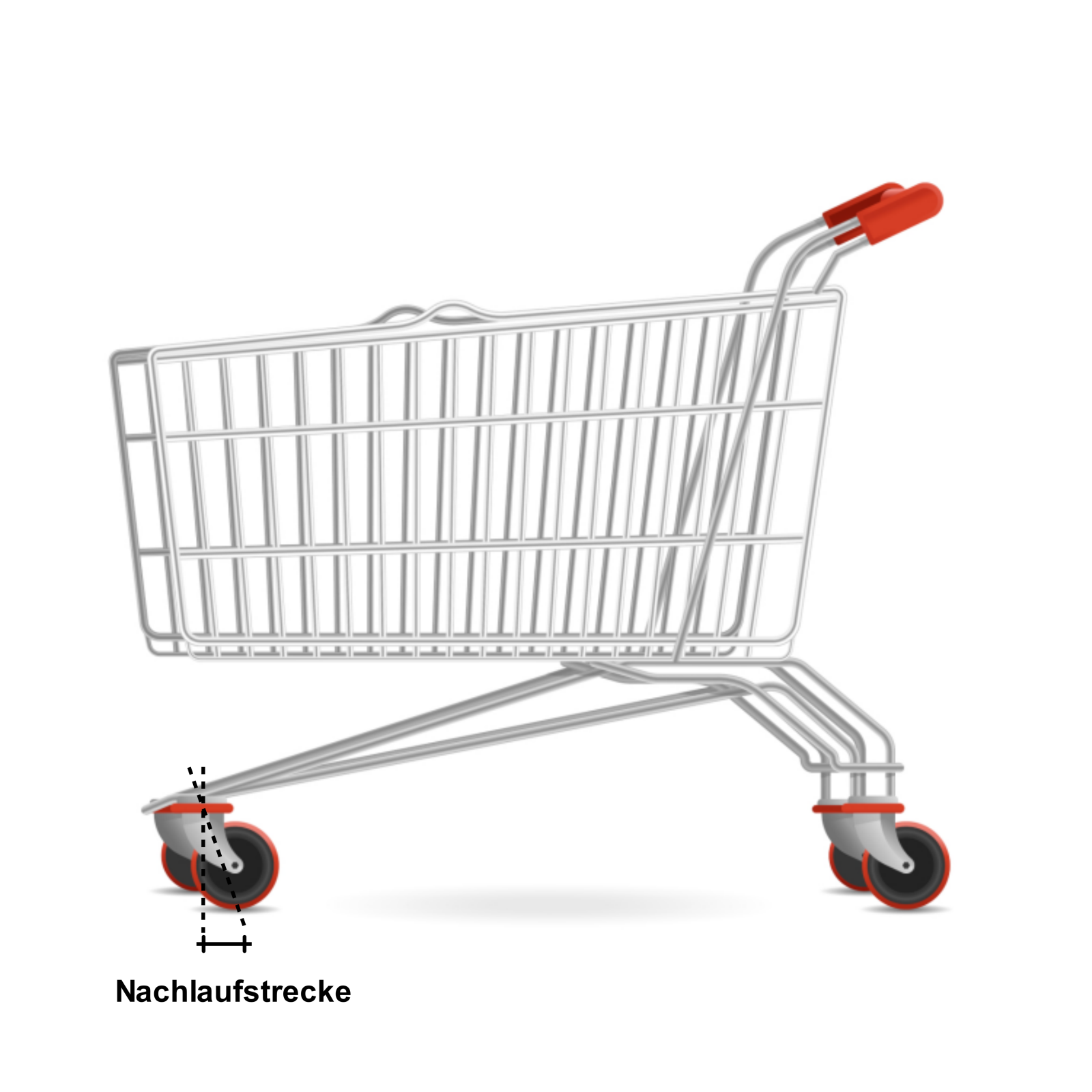
Designed by fullvector / Freepik
Caster is defined as follows. The axis about which the wheel pivots is extended until it crosses the road. The distance from this point to the centre of the tyre’s contact patch is the caster trail. If the point lies in front of the contact patch, the caster is positive; if it lies behind it, it’s negative. Caster is only of importance for the steered axle, and vehicles with rear-wheel drive always have positive caster.
With steered solid axles, this is achieved in that the axis about which the wheel pivots stands slightly at an angle. The joints that form this axis thus don’t stand perpendicular to the road.
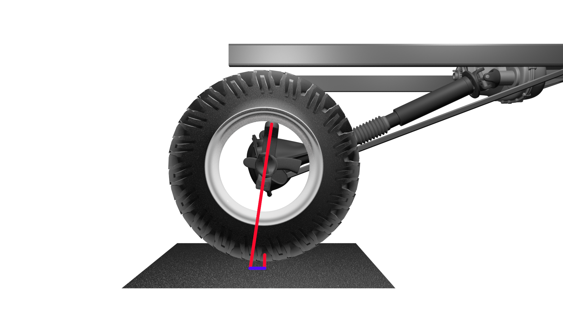
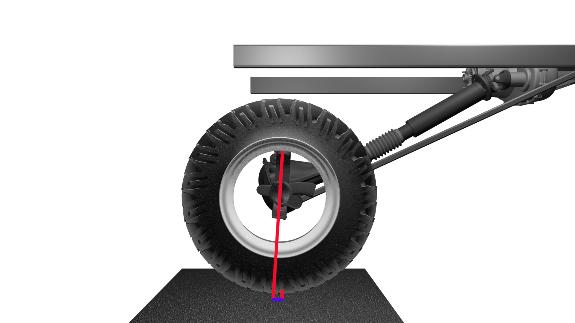
The caster ensures good directional stability and it’s the decisive force that, after turning in, ensures the automatic return of the steering to straight-ahead. It mustn’t be too large and not too small. If it’s too small, the steering resistance and the restoring forces decrease. The steering feels unstable and fluttery, the feel for the steering gets worse due to the lower resistance. If it’s too large, the steering seems heavy and sluggish.
Setting toe, camber and caster
With the exception of the toe setting on solid front axles, setting toe, camber and caster is a matter for professionals who also have the necessary measuring equipment for it. Anyone who’s nonetheless interested in how it’s done can read it here.
Setting the toe
With a solid axle the toe is very simple to set. In front of or behind the axle there’s the track rod that connects the front wheels and transfers the steering movement from one wheel to the other. The track rod is in two parts, and one part is screwed into the other. A clamp or similar secures this connection. To set it, you undo the clamp and turn the track rod to change the length, to the required value. This is often given in millimetres by which the rim flanges have to stand closer to or further from each other.
After undoing the clamp, you only need a rod that corresponds to the distance of the inner rim flanges at zero toe, let’s say for example 1860 mm. If the manual gives a toe out of 2 mm, you measure with the rod centrally at the front rim flanges, since with toe out they stand further apart there. The rod is held horizontally between them and placed against one rim flange at the height of the centre of the wheel hub. On the other side there then has to be a gap of 4 mm between the rod and the rim flange. Alternatively a rod of 1864 mm can be used, which then has to fit exactly between the rim flanges.
With vehicles with independent suspension there isn’t the one track rod. There the toe is set via the separate steering rods to both sides.
Setting the camber and the caster
On a vehicle with a solid front axle, neither camber nor caster can be set. Both are predetermined by the position of the kingpin.
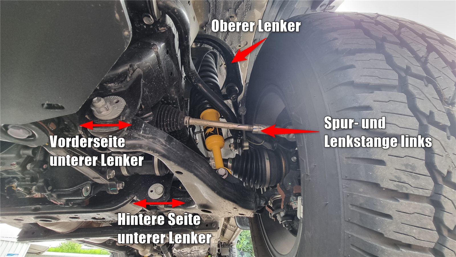
With vehicles with independent suspension and several arms, screws are provided for this on the lower arm. It’s attached with two points to the body and one to the wheel carrier. With them, camber and caster are set at the same time. These screws have an oval disc that, when turned, moves the arm outwards or inwards at the respective attachment point. With the scale on the screw, the set value can easily be transferred from one side to the other.
Before setting, the current values are to be determined with the appropriate measuring equipment. In the workshop manual you then find the values that have to be observed and how you have to turn the screws. On the lower arm, the following scheme results for the setting:
| Parameter | Front of the arm | Rear of the arm |
|---|---|---|
| Increase caster | move inward | move outward |
| Decrease caster | move outward | move inward |
| Increase camber | move inward | move inward |
| Decrease camber | move outward | move outward |
| Increase caster and camber | move inward | – |
| Decrease caster and camber | move outward | – |
Want to know more?
Anyone who wants to work their way deeper into the subject is recommended the books “Chassis Handbook” and “Race Car Technology Basic Course” from the Professional series of the Springer Vieweg publishing house.
Image by macrovector on Freepik