Another fault message in the display? The engine just went into limp mode? Often these things are connected with the engine or exhaust sensors. Either because they’ve spotted a problem or are the problem themselves. So they’re happily cursed, but in modern engines they’re indispensable. Which sensors there are, what they’re for, how they work and which faults they can be responsible for, you can read here.
Our fleet ranges from 1971 to 2024. Over this span of more than half a century we can follow well how electronic vehicle control gradually arrived. In our vehicles from before the 1980s there aren’t even electrical sensors. Temperature and pressure are still passed directly to the gauge via capillary lines, the speed transmitted to the speedo via a turning shaft. The only exception is the fuel sensor, which already works electrically. From the mid to late 1980s came petrol injection with electronic control units. For the American market, certain emissions figures now had to be met. There we already find the first engine sensors monitoring engine position, air and temperature.
Our vehicle from the early 2000s doesn’t have many more sensors than these older vehicles, and also only a single sensor (crankshaft sensor) that can really shut the engine down. But the stricter emissions standards demand ever closer monitoring and already require electronic control of the injection. Fuel, coolant and intake air temperature join as input signals for the control.
In the vehicles from the mid-2010s to today, the full programme is then found. Diesel particulate filter, catalytic converter and other exhaust after-treatment systems, plus electric engine cooling, need the whole range of measuring and control technology, because that’s what it is in the end: measure & control.
The sensors are the eyes and ears of the electronics. Without the sensors it can’t control the engine and ancillary units. We want to limit ourselves to that here, the engine and the exhaust system that belongs to it. Because if we listed all the sensors otherwise in the car, the list would be near endless.
I have a divided relationship with this tech. Leaving the environmental aspect aside and looking at my Land Rover Td5 engine from 2002 with a control unit, I find it very well done. Only through electronic control are more power, less consumption and better emissions possible. On the other hand it takes just one working sensor for the engine to run. The electronics even protect, as I know from my own experience. Unnoticed, the engine got too hot more than once and the ECU put it into limp mode, which prevented damage. That can’t be bad. Without the ECU it might have been noticed too late. With this generation of vehicle I’d still say, a control unit is easier to swap than a differential is to repair.
But in the vehicles of the last two decades I find there are too many dependencies and too much complexity. But maybe the status-quo bias is at work here: every generation accepts the status quo and prefers it to changes. So these things creep in, get accepted and count as normal from then on.
Introduction to the topic
A current vehicle easily reaches 50 to 60 sensors and more.
A classification of the sensors looks like this (in brackets the usual number):
- Position and angle sensors (11)
- Speed sensors (5)
- Vibration sensors/gyrometers
- Flow sensors (1)
- Acceleration and vibration sensors (7)
- Pressure sensors (22)
- Temperature sensors (many)
- Torque sensor
- Force sensors
- Concentration sensors (2)
- Optoelectronic sensors (2)
Most sensors are found in the area of engine management, primarily for reducing and after-treating emissions. They measure states, monitor them, adjust and, if needed, alarm too. This is about those sensors. They’re divided below into the categories above and it’s explained how they work. Some sensors have developed further, become more precise and robust (e.g. with the switch from potentiometers to Hall sensors), or several principles are in use in parallel.
Not every sensor is in every car, and especially with exhaust after-treatment, different methods can be in use, controlled and monitored in different ways. But basically the trend can be clearly shown that, with rising demands on exhaust after-treatment, the sensor count has increased a lot, to make the control ever tighter and more precise.

DTC fault codes
In what follows we give the DTC fault codes for the individual sensors. Besides the maker-specific codes, these are uniform fault numbers that can be read out via the OBD port, e.g. with an OBD2 adapter. There are currently about 11,000 fault codes, defined in the SAE J2012 and ISO 15031-6 standards.
The fault codes are divided into top-level groups:
The first letter stands for the DTC family:
- P: Powertrain – this includes engine and gearbox
- C: Chassis
- B: Body
- U: User Network / vehicle network
The letter is followed by the first number, which divides the further digits into general or maker-specific faults.
- 0: General fault
- 1: Maker fault
The last three digits then lead to the individual affected system. These can be hexadecimal numbers running from 0 to 9 and then from A to F.
- 0, 1, 3: Air and fuel metering
- 3: Ignition
- 4: Emission control
- 5: Engine idle control
- 6: ECU
- 7, 8, 9: Gearbox
- A, B, C: Hybrid drive
Speed sensors
Crankshaft sensor
One of the important sensors is the crankshaft sensor. It tells the control unit how the crankshaft stands and what speed it has. What it can’t know is when which piston has to be ignited, that is which is just on the compression stroke on the way to the power stroke. That’s because on a four-stroke engine, two crankshaft revolutions are needed for all four strokes. The crankshaft sensor does know when a revolution is complete, but not whether this revolution is bringing, for example, piston “1” into ignition position or whether the exhaust stroke is due. On both strokes the piston goes from bottom to top, but which stroke now follows, the sensor can’t report.
On engines like a unit-injector engine, for example, where a camshaft mechanically connected to the crankshaft decides when and which injector injects, the crankshaft sensor is enough. It gives the speed and helps calculate the injection length. Which injector injects when is controlled mechanically via the camshaft for the pump elements.
Engines that don’t couple the ignition or injection timing mechanically but control it only electronically need a further sensor to know when which cylinder is due for ignition: the camshaft sensor. Only that way can the control unit determine the right ignition or injection timing for the individual cylinders.
Crankshaft sensors are found in two versions. Either as a Hall-effect sensor, recognisable by three connecting wires, or as a magnetoresistive type with two wires. Opposite the sensor turns a toothed wheel with one tooth missing. Thanks to the regular arrangement of the teeth, the sensor can tell at all that the engine is turning and what the current speed is. The missing tooth then triggers a signal that tells the ECU a certain position. This is usually piston cylinder 1 at top dead centre (TDC). The signal of the missing tooth can also be seen as a regular reset, a synchronisation point.
The trigger wheel has to be connected somewhere to the crankshaft and turn with it. The sensor has to sit close to the trigger wheel. The whole thing is found either at the flywheel, at the crankshaft pulley or at its timing-chain or belt wheel, which normally sits behind the timing case cover. It’s worth carrying this sensor as a spare part in any case.
Usual fault symptoms are:
- Engine doesn’t start or cuts out again right after starting
- Misfires
- Jerky acceleration
- Rough idle
- Increased consumption
Typical fault code: P0335
Camshaft sensor
As the camshaft turns at half the speed of the crankshaft, one revolution corresponds to all four power strokes. So the camshaft sensor knows exactly where each piston stands and which is the next stroke for it. It determines the ignition or injection timing. The crankshaft sensor’s values can also be validated via it. If the camshaft is adjustable, several sensors are often present, otherwise one is enough.
Technically the camshaft sensor works like the crankshaft sensor. The sensor is found near the camshafts, usually in the rocker cover or the timing case cover. With Hall sensors the position can be determined exactly right when switching on, no rotation is needed to first determine the position.
Usual fault symptoms are:
- Engine doesn’t start or starts poorly.
- Misfires
- Jerky acceleration
- Rough idle
- Increased consumption
Typical fault code: P0340
Position and angle sensors
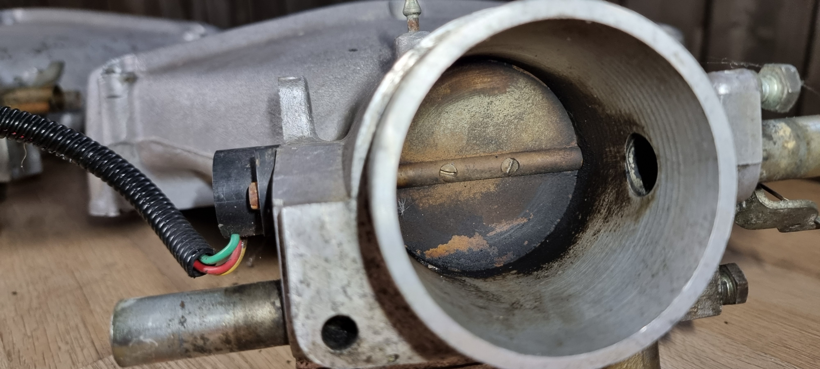
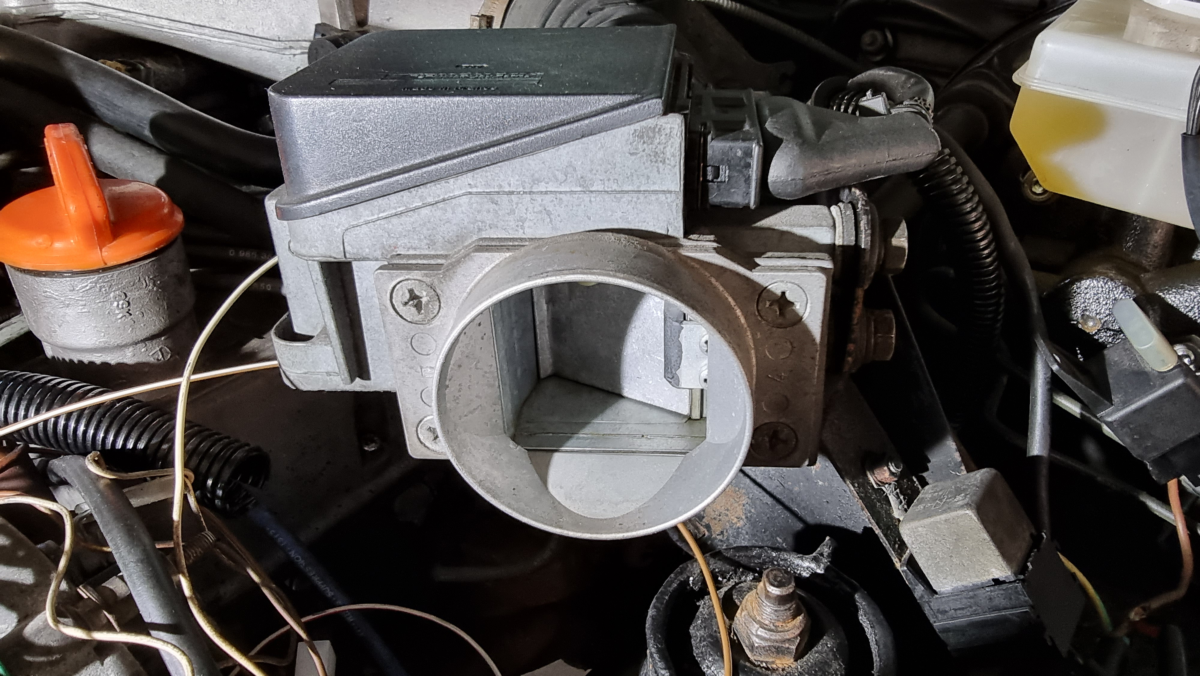
Throttle position sensor
Whether the throttle is still set mechanically or electrically, its position tells the control unit something about the current load. The throttle determines the possible air flow to the cylinders (not the actual one). The further it’s open, the more air can flow into the cylinders. If you drive at 80 km/h without a trailer, you press the accelerator less to hold the speed than if you’re pulling a 2-tonne trailer. That gives the ECU a clue about the load to be handled.
The throttle position sensor is a simple potentiometer sender, that is a variable resistor. Depending on the position, the incoming voltage is reduced and output again. The voltage level then tells the ECU what the opening degree of the flap is.
The sensor always sits at the throttle. The throttle is found between air filter and intake manifold. All the air flow has to pass through it, which is why it’s usually arranged close to the engine just before the fanning-out to the individual cylinders. The flap has a shaft via which it’s set. This shaft is mechanically connected to the accelerator or to an electric actuator controlled by the accelerator. The potentiometer sender is also connected to the shaft and turned by it. In modern vehicles, where the throttle is set electrically, the sensor is integrated into the actuator.
Usual fault symptoms are:
- Unwanted acceleration
- Hard engine starting
- Idle too low or too high
Typical fault codes: P0122, P2135.
Diesel engines and throttles
Now one or two of you may have wondered why a diesel engine has a throttle? Briefly for those who can’t place it: a petrol engine is controlled via the throttle. When you give it gas, you open the throttle and more air can reach the cylinder. As a result the car accelerates. On a diesel, though, you control the injection with the accelerator to accelerate, not the air. And yet diesels have throttles.
But the throttle only arrived on diesels with exhaust gas recirculation. It creates more or less vacuum, which was needed to control the EGR valve when these were still vacuum-controlled. Today all this happens via electric actuators and on the diesel the throttle stands fully open almost all the time. It only serves a little for quieter engine running at idle and on the overrun, as well as for cleanly shutting the engine off. Then there’s also the case where each cylinder has two air inlet openings in the cylinder head, one of which each has a flap that can be opened and closed. The vacuum for this control also comes from the throttle.
Accelerator pedal sensor
The accelerator pedal sensor replaces the cable, or before that the linkage, that formerly operated the throttle in the carburettor or the control lever on the diesel injection pump mechanically. The driver’s wish is determined via potentiometers set by pressing the pedal. To rule out errors, two opposing potentiometers are used to validate the signal. When the pedal is pressed, the voltage is reduced by one potentiometer while it’s increased to the same degree by the other. So the control voltage always stays at the level of the input signal when working correctly. The input signal is usually 5 V and both signal voltages always have to add up to 5 V. Then the signals are correct and the pedal position can be detected properly.
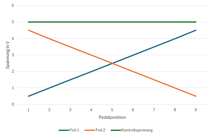
As potentiometers are sliding contacts, they’re subject to mechanical wear. So these were replaced by contactless Hall sensors, where a rotor is moved opposite a coil and so produces a signal.
Through the mechanical decoupling of the accelerator from the throttle, the control unit can also override our driver’s wish. Our wish is no longer transmitted directly and immediately, but handed over to the control unit. If this has put the engine into limp mode, for example, it ignores our wish and limits the speed, no matter how far we press the pedal. In this way the speed can also be capped at the top, or in critical driving situations the acceleration not happen as the driver wishes.
Through the use of electronic accelerators, smoothing also happens. With a mechanical connection, especially with a linkage, engine movements and slight foot movements act directly on the throttle. With carburettors that can increase consumption, as these have a pump that pumps extra fuel into the intake when the pedal is pressed, to allow short-term power demands. With an electronic signal the control unit can take these unwanted smaller movements out of the signal and so smooth it. The engine running is thereby calmed and made more economical.
Usual fault symptoms are:
- No throttle response
Typical fault codes: P0120 to P0124, P0220 to P0229.
Flow sensors
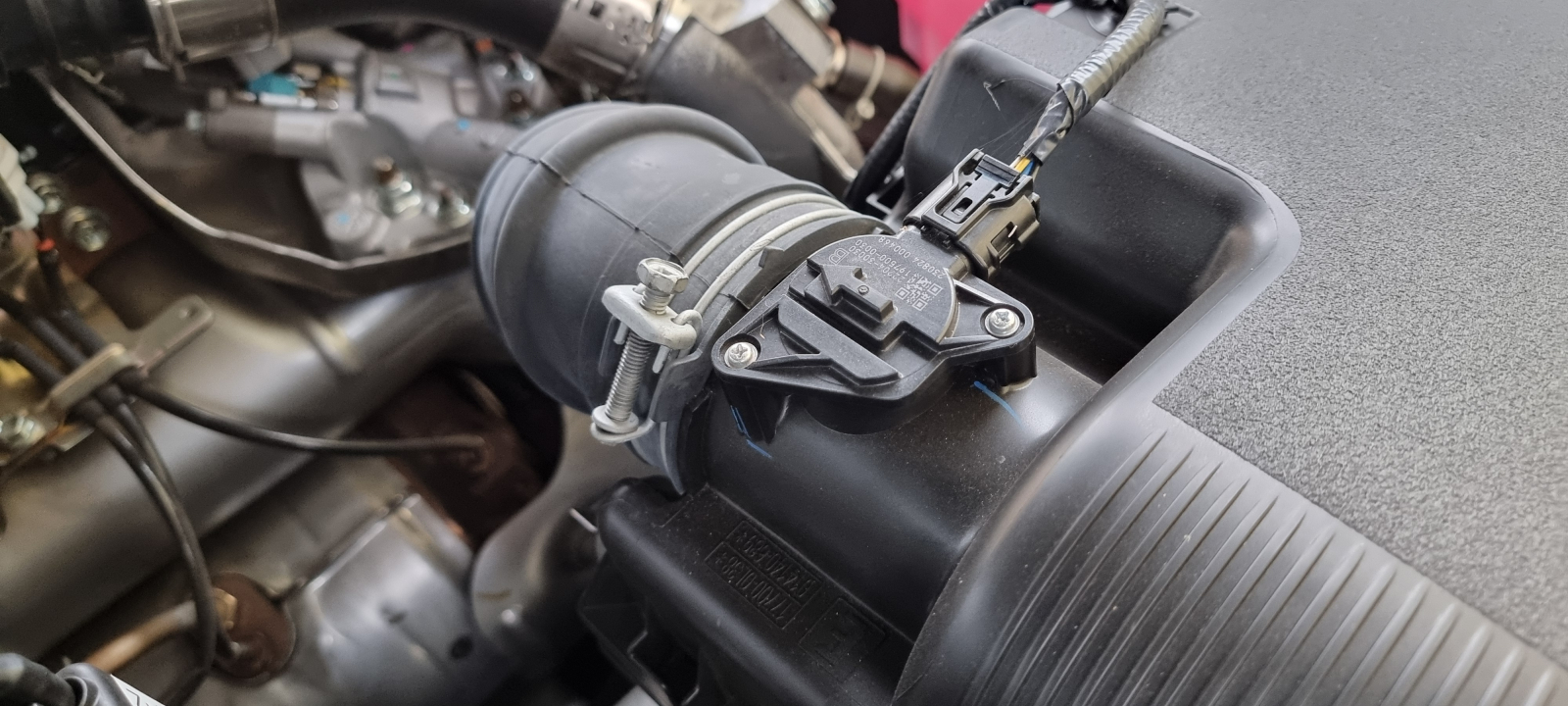
Mass air flow sensor (MAF)
While the camshaft sensor tells the control unit when to ignite or inject fuel, the mass air flow sensor tells it how much it has to be. The control unit always tries to give the right amount of fuel to the air amount, to give the respective best ratio depending on load and fuel type. To know the air amount, the mass air flow sensor is needed.
Stoichiometric ratio
To achieve the best possible combustion, a certain ratio (lambda λ) of air to fuel molecules has to be produced. The ideal ratio is called the “stoichiometric ratio”. It’s a mass figure and is reached at lambda λ = 1. When this is set, every fuel molecule finds exactly the right amount of oxygen reaction partners. The ideal air-to-fuel ratio is 14.7:1 for petrol and 14.5:1 for diesel. Combustion engines should always be run tightly around λ = 1, as this allows the exhaust cleaning. We’ll come back to that with the O2 sensor.
That shows that it’s not the air volume or the density alone that matter, but the mass. The mass is connected to the volume and the density, which is why older measuring methods (AFM, Vortex and temperature) measure these parameters but then have to infer the mass. Only the MAF actually measures the mass and is best suited to this purpose.
Technically the air mass is measured by two methods. Both methods are based on the change in the electrical resistance of a metal like tungsten or platinum. One method works with a wire and is therefore called “hot wire”. It’s the older method. Here a wire is exposed to the air flow and a second lies protected as a reference. The underlying principle is that the air molecules cool the wire and change its electrical resistance. The resistance determines the current flow through the wire and that gives the signal.
The second principle uses a film with conductor tracks, hence called “hot film”. These are also heated by current and cooled by the air molecules. Because several conductor tracks, and so two sensors, lie next to each other, this sensor can even determine the direction of the air flow. Depending on which of the two sensors cools first, the air is just flowing in or out. On combustion engines there’s a pulsation. Here the air doesn’t only go towards the engine, it pulsates and moves in pulses, away from it too. This information can also be used by the ECU for better control of the combustion.
The good thing is that, unlike the two following, older methods of determining the air mass, the MAF automatically includes altitude and temperature changes, or is independent of their values, as both affect the air mass. No separate temperature measurement is needed to determine the air mass.
You’ll find the MAF sensor directly after the air filter housing. The grille in front of the measuring unit, by the way, isn’t only meant to keep dirt out, it smooths the air flow so that the very small part that flows past the sensor can actually be scaled up to the whole air mass.
Usual fault symptoms are:
- Engine doesn’t start
- High consumption
- Poor acceleration
- Stuttering engine, brief misfires
Typical fault codes: P0101, P0102.
If you notice one of the symptoms, it’s worth cleaning, especially with hot-wire or hot-film sensors, with brake cleaner and a bit of compressed air. Often the sensors are just dirty. They react very sensitively to that, any contamination falsifies the measurement considerably. It’s strongly advised against using an aftermarket air filter that has to be oiled in front of these sensors. Even the smallest oil drops carried along contaminate the sensor.
Normally the ECU needs the signal from the mass air flow sensor. There are engines where the sensor can be disabled and the engine still works. That’s often the case with engines where the sensor isn’t strictly needed for engine control but primarily for keeping to the emissions figures, as on vehicles in emissions classes 2/3. If you simply pull the plug, the ECU uses a default value. As a result the emissions worsen, but the engine stays fully functional.
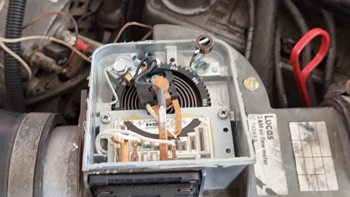
Air flow meter (AFM)
The air flow meter serves the same purpose as the mass air flow sensor, but a different principle underlies it. This type was used at the dawn of the first injection engines in the 1980s, but has been replaced for many years by the MAF sensor, as the latter measures the air mass directly.
With the air flow meter the air flows through a chamber and moves a spring-loaded flap. So the flap reacts to the air speed and its density. To increase accuracy, the AFM is often coupled with a temperature sensor, to better infer the density of the air, which in turn lets the air mass be better inferred. The purpose is to mix the right amount of fuel into the air, and this ratio refers to the air mass, not the volume or density.
The flap has a second vane that moves into a closed chamber. The air cushion created cushions the flap movement. This flap mechanism is connected via a shaft to a potentiometer, on which a voltage value is set according to the air amount.
It’s found between air filter and throttle and always has to be mounted horizontally. Any other position would also subject the spring-loaded flap to gravity. Just imagine the car driving over a bad stretch and every bump leading to a flap movement. Another disadvantage of this system is that the flap acts like a throttle. It restricts the air flow and sets a resistance against it, even if a small one.
As the AFM was used before the introduction of the OBD2 port, there are no uniform fault codes.
Exotic: Karman Vortex air flow meter
Also in the 1990s, Vortex sensors were built into some vehicles to determine the air mass. They’re based on the principle of creating air vortices. For that, a mostly triangular obstacle was built into the air flow that causes the vortices. The frequency of the vortices created is proportional to the air amount flowing through. The vortices are measured after the obstacle, the “vortex generator”, by an ultrasound signal or a metal foil. These move an LED that shines onto a phototransistor. Through the changing light incidence, the transistor produces a signal for the control unit. The signal gives the speed of the air. Together with the known volume of the housing, the air mass can be determined.
Pressure sensors
Many pressure sensors work on the same principle, which allows great freedom in size and shape. It can also be designed for measuring one pressure or as a differential pressure sensor subjected to two pressures.
The principle is a thin membrane with four etched-on strain gauges. Of these, two each are stretched and two compressed on pressure changes. The resistors are connected into a so-called Wheatstone bridge, which allows very precise measurements. On one side is a silicon chip into which the membrane is pressed as the pressure rises. On the other side is the medium whose pressure is to be measured.
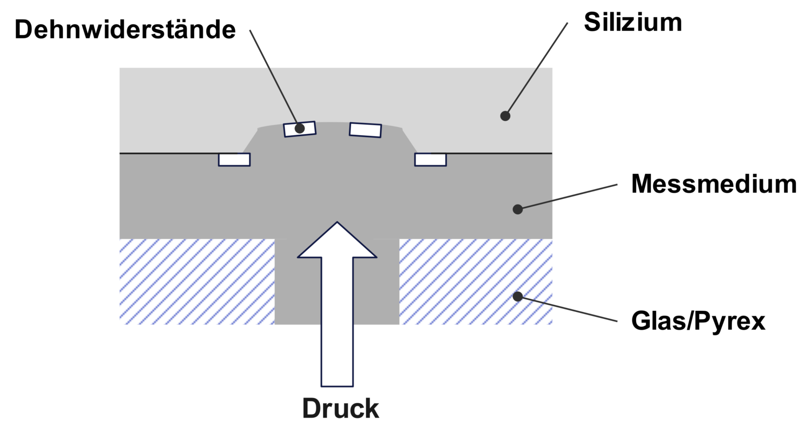
Other pressure sensors act with the membrane on a piezo element that produces an electrical voltage according to the pressure.
Manifold absolute pressure sensor (MAP)
MAP stands for “Manifold Absolute Pressure”. This sensor measures the air density in the intake manifold via the air pressure. Just like the MAF, the MAP compensates for temperature and altitude and needs no separate measurement to determine the air mass.
As the MAP sensor does the same as the MAF, the question arises why engines have both? On naturally aspirated engines the measurement simply gets even more precise. On forced-induction engines (turbo) it serves to monitor the intake lines, because a difference between the incoming and arriving air points to a problem. In addition, very complex air movements arise on forced-induction engines through the throttle, the turbocharger and the engine pulsations. To get a better picture of this and, for example, better control a variable-geometry turbocharger, both sensors are needed. On diesels the EGR valve comes in too, whose function is also monitored by the combination of both sensors.
As the pressure is measured in the intake manifold, the sensor is always found there too.
Usual fault symptoms are:
- Engine doesn’t start
- High consumption
- Poor acceleration
- Stuttering engine, brief misfires
Typical fault code: P0106.
Anyone who increases their engine’s power and raises the boost pressure for it often has to have a different MAP sensor too, if the pressure exceeds the range of the original sensor.
Diesel particulate filter differential pressure sensor
The exhaust flows into the particulate filter on one side and out on the other. There’s a pressure sensor on both the inlet and the outlet side. If the difference between the two gets too large (well over 1 bar), a particulate filter regeneration has to be started.
There’s a second method too that’s often coupled with the differential pressure method. It’s a purely computational method, where the soot load is calculated from the driving situations and the exhaust amount.
Ash load
It’s important to know that despite regeneration of the particulate filter, it has to be swapped or cleaned at some point. While the soot particles burn off completely through the rise in exhaust temperature, residue from oil combustion, engine particles and other substances stays permanently in the filter as ash. That leads at some point to a permanent blockage, which brings knock-on damage, for example to the turbocharger. So the particulate filter should be kept an eye on too.
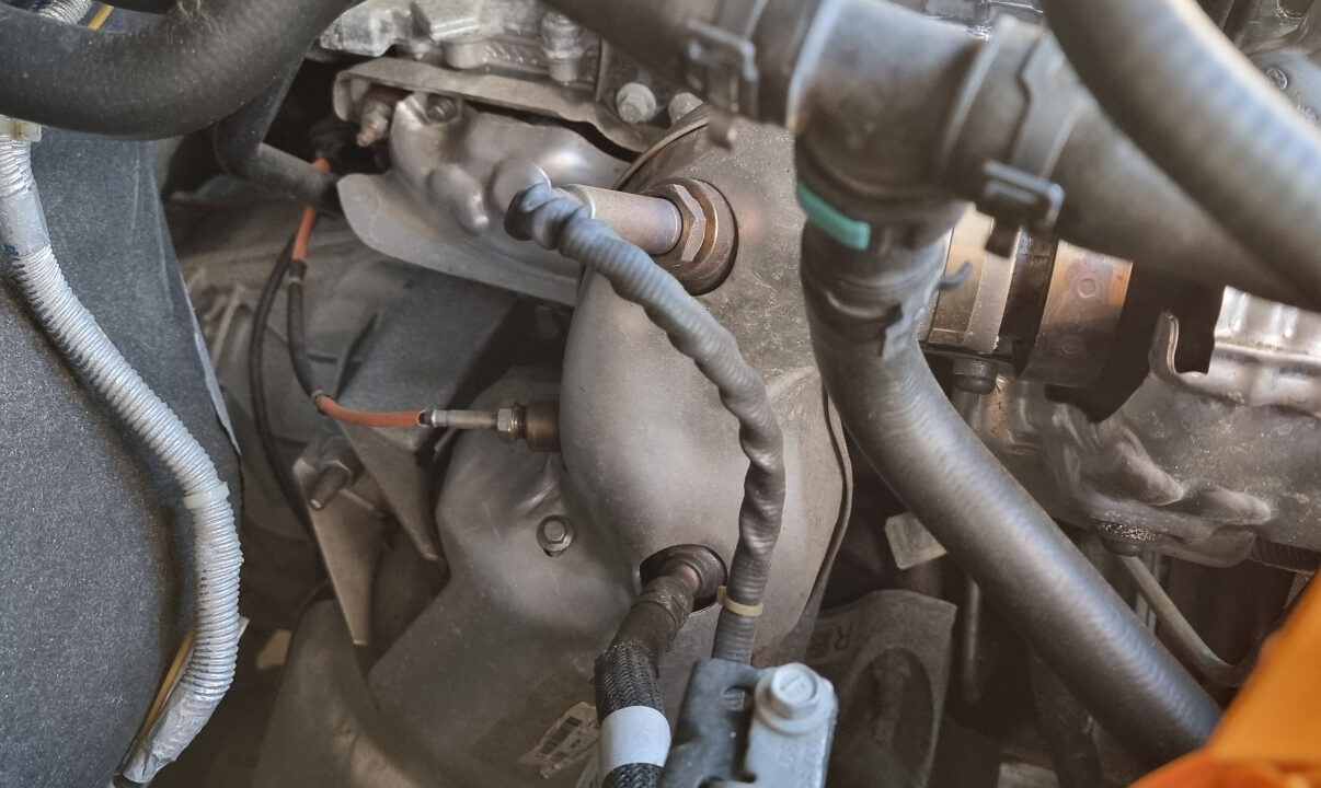
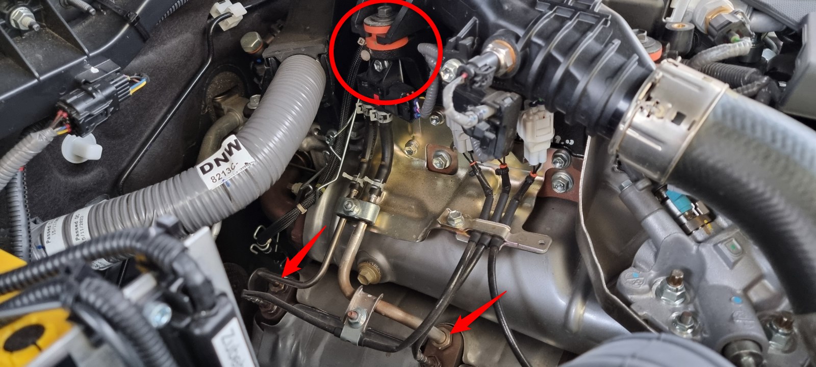
Oil pressure sensor
This is one of the most important sensors in the engine. It isn’t needed for operation, the engine runs without it and doesn’t use its values for control, but it’s extremely important for monitoring. If not enough oil pressure is available, for which there can be various reasons, damaging wear occurs, or in a very short time considerable damage up to total loss of the engine.
While in the past the oil pressure was shown as a value on a gauge, today sadly only oil pressure switches are found. The oil pressure switch alarms when a predefined value, usually around 0.5 to 0.7 bar, is undercut. This value is often chosen very low, almost too low. If the oil pressure warning light comes on, you should react very quickly, stop and shut the engine off promptly. On no account drive on!
Anyone who still has a gauge may count themselves lucky. Here you can watch the oil pressure over a drive, various seasons and outside temperatures and the oil’s usage period and draw your conclusions. You can always adjust your engine revs so you have enough oil pressure. That also lets you tell when the oil pump’s pressure relief valve is damaged and the oil pressure is therefore permanently too low. Anyone without an oil pressure gauge should be told it’s a sensible measure to retrofit an oil pressure gauge with a combined warning switch. With this instrument, brewing problems in the engine lubrication can be spotted early.
More on that, and why an oil pressure gauge is very sensible, you’ll find in our article on extra instruments: extra instruments.
The oil pressure sensor can be fitted anywhere on the engine. If only one wire goes to it, it’s an oil pressure switch that, when triggered, simply connects through to the battery’s earth via the engine block. It can also be a sender without a warning contact. If two wires go to it, it’s an oil pressure gauge with a sender and warning circuit.
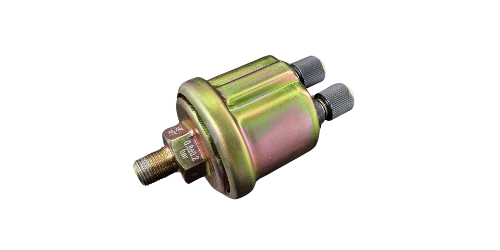
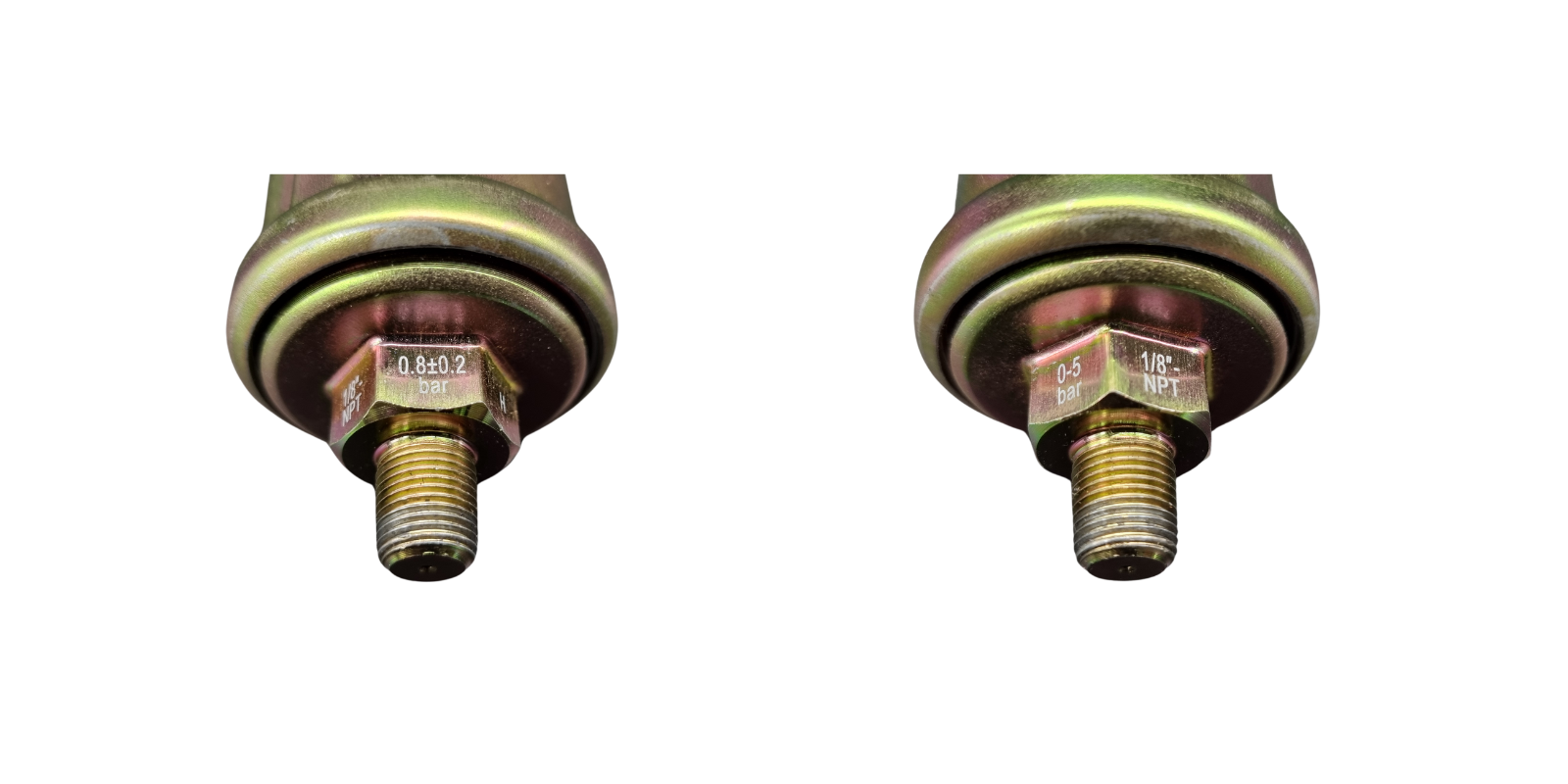
On a retrofit oil pressure sender there are figures for the thread (e.g. 1/8″ NPT), for the measuring range (e.g. 0-5 bar) and, if a warning contact is present, when it alarms: (e.g. 0.8 bar)
There are no typical fault symptoms. Too little oil pressure shows up in damage that builds up slowly, or in the immediate failure of the engine. Make sure the oil pressure warning light comes on when you switch on the ignition. That lets you check whether it works. As long as the engine isn’t running, there’s no oil pressure. After the first few revolutions it has to go out.
Typical fault codes: P0520, P0521, P0522.
Vehicles without a dipstick
You should check the oil level regularly anyway, as it’s not only important, but this check can also inform you of other problems. So it’s better if your engine still has a dipstick. Sadly that’s increasingly not the case. Because if the oil pressure warning light comes on, the dipstick is the only and surest check option you can use without further help and tech.
Anyone who only finds a digital display in their vehicle has to rely on the measured results. There are sadly enough examples where false alarms were triggered or owners were told to top up an amount X. But too much oil can also be very harmful. Anyone who can’t check the true state with this very simple and absolutely sure dipstick has to do an oil change to ensure the correct oil amount.
If sensors detect that there’s too little oil, they usually prevent driving on. The car has to be towed. Very annoying if it’s a false alarm. Checking via the sensors isn’t simple either. The manual and the display give instructions on how the car has to stand (level) and whether, for example, a set engine speed has to be held while stationary and so on. And it could be so simple.
Fuel pressure sensor
The pressure of the fuel has to be measured too. That depends on the engine type, though. Common-rail injection engines need the sensor to determine the pressure in the rail. All injectors are connected to this “rail”, which is permanently supplied with fuel and pressure. Only that way are the various injections possible. On a modern engine that can be up to eight(!) per power stroke.
So during the cleaning of the diesel particulate filter, for example, diesel is injected into the cylinder again very late, so it burns only late. That makes the exhaust temperature rise to the needed value. These pre- and post-injections only work if the injection is mechanically decoupled from the engine speed and a high diesel pressure is always present.
So that the control unit knows, at a given pressure, load and all other values, how long the injection has to take to reach the best air-fuel ratio, the pressure has to be known. So you’ll always find the sensor at the rail, the common line above the injectors.
Usual fault symptoms are:
- Poor engine starting
- High consumption
- Poor acceleration
Typical fault codes: P0190, P0193.
The madness in numbers
To picture what a modern common-rail direct-injection engine achieves, here’s a little calculation:
You drive at a speed of 2,500 revolutions per minute. That’s a common value for a diesel engine. That means each engine revolution (360°) takes 0.024 seconds = 24 milliseconds. On a four-stroke four-cylinder engine there’s a stroke change every 180°: intake > compression > power > exhaust. At 2,500 revolutions the stroke change then happens every 12 milliseconds.
The injection on a direct-injection engine starts at the earliest in the second half of the compression stroke and so has a maximum of 6 milliseconds for the injection of all the fuel needed. At 3,500 revolutions that reduces further to 4 milliseconds. For comparison, a blink of the eye takes about 100 to 150 milliseconds.
That’s also the reason, by the way, why direct-injection engines are limited to speeds of around 6,500 revolutions per minute. After that there simply isn’t enough time, at the injection pressures currently possible, to inject the amount of fuel needed.
Temperature sensors
Most temperature sensors work with thermistors, electrical resistors whose resistance value changes depending on the temperature. These resistors use metals, metal oxides or silicon for that, depending on the design. So in what follows we only go through the purpose.
Intake air temperature sensor (IAT)
To achieve an even more efficient mixture and thereby less emissions and consumption too, the temperature can be added to the data on the air mass (MAP, MAF, AFM). As colder air contains more oxygen than the same amount of warmer air, the injection amount can be optimised further.
The measured temperature lets the air density be inferred. Often it’s integrated into the AFM or MAF. If it’s not found there, it’s fitted at another point in the intake tract, usually near the throttle.
Usual fault symptoms are:
- Rough engine running
- Power loss
- Jerking
Typical fault code: P0113.
Oil temperature sensor
Besides the pressure, the oil temperature is of interest too. In the gearboxes too, by the way, but that’s not the topic here. Oil gets thinner with rising temperature, which you can observe via the oil pressure sensor, because the oil pressure drops for a while after the engine start until the oil has reached its operating temperature. If the oil temperature sensor reports its values to the ECU, these can, just as with the coolant, put the engine into limp mode or prevent the engine starting.
The cause of oil temperatures that are too high can be too little oil, combustion that’s too hot or disturbed oil cooling. That should then be reflected in the coolant temperature too. No symptoms can be directly detected in the engine running or driving behaviour of the vehicle.
Usual fault symptoms are:
- Engine limp mode
Typical fault codes: P0196, P0197, P0198.
Fuel temperature sensor
As with the air, the temperature of the fuel has an influence on its density. Cooler fuel is less dense than warmer. So with cooler fuel a bit more has to be put into the combustion.
The temperature sensor is somewhere in the fuel system, usually at the pump or the filter. There can also be two sensors. Faults are only hard to spot, as a fault doesn’t clearly affect driving.
Usual fault symptoms are:
- Emissions test not passed
- Increased consumption
Typical fault code: P0183.
Coolant temperature sensor
In the past the sensor only served to show the driver, and the interpretation lay solely with them. Fine, until white clouds of steam rose from the engine. On vehicles with a control unit, the coolant temperature is included in the engine management. The temperature influences the amount of fuel given, but also controls things like the radiator fan, if it runs electrically. If the coolant is too hot, the sensor also puts the engine into limp mode to prevent damage like a blown cylinder head gasket. It can also prevent the engine starting.
In most cases the sensor sits directly in the coolant circuit. There are also vehicles that have several sensors. On some engines the sensor has no contact with the fluid. In those cases the water temperature is calculated depending on the measured temperature.
Usual fault symptoms are:
- Consumption too high
- Black smoke in the exhaust
Typical fault codes: P0116, P0117, P0118.
Exhaust gas temperature sensor (EGT)
We mostly find this sensor in diesels. It measures the temperature of the exhaust, and if there’s only one, it sits as close to the engine as possible in the exhaust manifold. Today’s vehicles mostly have more exhaust temperature sensors, easily four or even more. The exhaust temperature is directly connected with the change in the fuel-air mixture, which can be monitored this way. The sensor can protect the turbo and the catalytic converter from damage through overheating. Especially on engines with a power increase it’s the most valuable sensor for giving the driver important information. In motorsport, “not gas-proof” tunes are often used. The full power of the engine may not be used carelessly over longer periods. Experienced drivers use the exhaust temperature display to decide when and how long they drive at high power.
On the particulate filter the sensor is used to allow its regeneration. If a regeneration is due, the exhaust temperature is raised by late injection of fuel. When it reaches the necessary temperature, the sensor can let the process start.
Usual fault symptoms (on the diesel) are:
- Power loss
- High consumption
- Long DPF regeneration
- Frequent DPF regeneration
Typical fault codes: P0405, P0546, P2032.
Vibration sensors
Knock sensor
“Knocking” (also called “pinking”) is a dreaded state of petrol engines, as it leads to engine damage in a short time. Colloquially two causes are described as “knocking”, as both cause this noise. The noise is perceptible and is reminiscent of a small hammer being struck on the engine.
The first cause is the uncontrolled, unwanted self-ignition of the petrol at various points in the combustion chamber. That creates extreme pressure and stress for piston, conrod and crankshaft. One reason for it is the wrong petrol grade (octane rating) for the respective engine and its compression ratio. The more strongly an engine compresses, the hotter the mixture gets and the more it tends to self-ignite. The knock resistance of petrol is defined by its octane rating. The higher the octane rating, the less the fuel tends to self-ignite. So highly compressed engines also have to run fuels with high octane ratings.
The second cause is premature external ignition. So the petrol doesn’t ignite through the compression itself, which sets in comparatively late. Ignition that’s too early can be even worse, as here the combustion can set in so early that it exerts considerable pressure against the piston rushing up. It also shows up through knocking noises. Pre-ignition can happen especially with direct injection, when the engine has low revs at high load. Glowing soot particles that hang on or fall from sooted valves, for example, or small oil splashes that get into the combustion chamber unwanted during the compression phase, can lead to premature ignition. Considerable damage that occurs quickly is the result.
Another reason for ignition that’s too early is the dynamic adjustment of the ignition timing. The ignition of the petrol always happens before the piston has reached its highest point (TDC, top dead centre). That’s necessary, as the combustion also needs a moment to develop force. So the faster the piston rushes up, the earlier the mixture has to be ignited. Then the point of greatest force development lies after TDC and can press the piston down. So the ignition timing is automatically advanced more and more with rising revs. The ignition timing is given in degrees before or after TDC. Usual values lie between 10° at idle and over 34° before TDC (advance) at maximum revs. 34° may sound like a lot, but in practice means only a few millimetres of the piston’s distance from TDC. By contrast, 50° or 60° before TDC would be a considerably greater distance, as 1° of rotation doesn’t mean the same distance everywhere.
If the maximum values are exceeded, or the current ignition timing doesn’t suit the fuel (octane rating) or the revs, knocking can occur.
The knock sensor is a microphone that reacts to the specific noise of knocking. As soon as it detects knocking, it makes sure the ignition happens a bit later again, or more fuel is given, which also counteracts pre-ignition. Here the cooling effect and the richer mixture play a role.
While in the past knocking was prevented by the correct setting of the distributor, or on ECUs by a corresponding ignition curve (ratio of advance to revs), with knock sensors the ignition timing can be dynamically brought ever close to the limit. That allows high power to be achieved without running the risk of damaging the engine through knocking.
Diesels can’t knock through unwanted pre-ignition, as they only compress air and no air-fuel mixture. The injection is controlled and comes at the right moment. On a diesel engine the problem is rather a late ignition. So diesel engines usually have no knock sensors. There are some models that have a similar sensor to measure the ignition start and, if needed, adjust the injection start within a narrow range.
The sensor has to be firmly bolted to the engine. In it is a ring-shaped mass. As it’s inert, it’s moved along in the rhythm of the engine vibrations. In doing so it presses on a likewise ring-shaped piezo element. These have the property of producing a voltage under pressure that can be measured. The vibration pattern of the engine is known to the control unit. If the engine starts to knock, the disturbed combustion chamber pressure produces vibrations and structure-borne noise. That transfers to the ring in the sensor, which gives off a correspondingly restless voltage trace there.
The sensor is always directly on the engine block. Four-cylinder engines have one, engines with six or more cylinders can have several sensors to reliably cover all cylinders.
Usual fault symptoms are:
- Knocking noises perceptible
- Warning light (if present)
- Engine switches into limp mode
Typical fault code: P0325.
Gas and concentration sensors
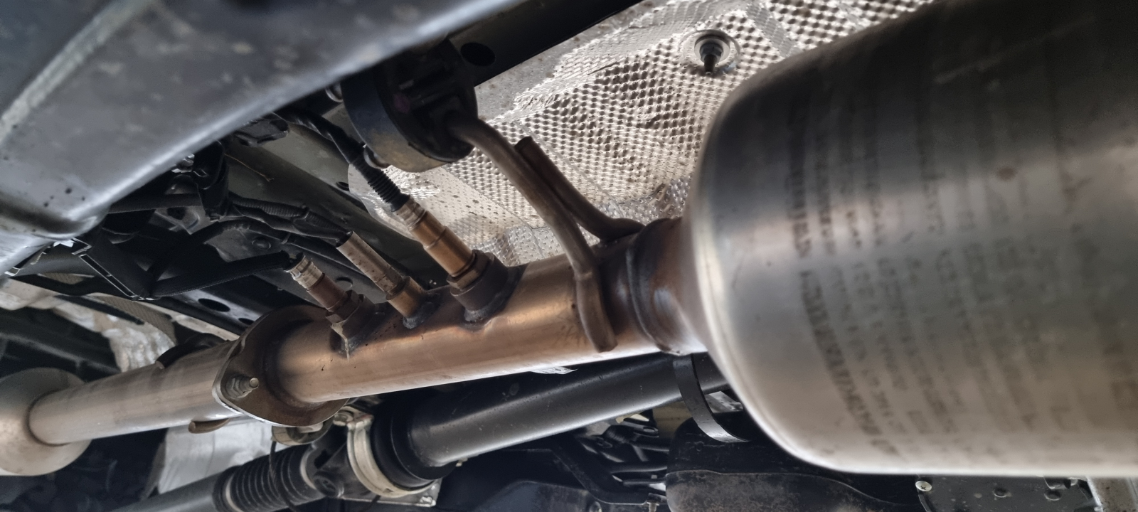
O2 sensor (lambda sensor)
As the name suggests, an O2 sensor measures the oxygen content. On cars this happens before (upstream) and after the catalytic converter (downstream). The sensor before the catalytic converter lets the fuel-air mixture (lambda) be inferred via the measured oxygen share in the exhaust. According to the measurement, more or less fuel is mixed into the combustion.
The aim is to keep to the ideal air-to-fuel ratio (λ = 1). The ratio of air and fuel is extremely important for the power and the pollutant amounts. So the oxygen sensor serves to check whether the ratio wished by the ECU was actually applied and the values are in the wished range.
There are two kinds of O2 sensors, the narrowband and the wideband sensor. The narrowband sensor can only give the ECU feedback on whether the mixture was “rich” or “lean”. The wideband sensor can additionally report the ratio. So it’s much more precise.
The structure of the sensor is somewhat complicated and there are various types. The basic principle is that the oxygen share in the exhaust (0.3 to 3%) is compared with that of the outside air (about 20.8%). Various coatings (zirconium dioxide, titanium dioxide) produce, depending on the difference, an electrical voltage that makes up the signal. At a residual content of 3% the fuel-air mixture counts as “lean”, at 0.3% as “rich”.
For operation one lambda sensor is enough. With the introduction of EOBD (US designation: OBD-2), though, the function of the catalytic converter has to be monitored too, which is why there’s a second sensor after the catalytic converter. Through the comparative measurement it can be detected whether the catalytic converter still works properly. Here the catalytic converter’s ability to store oxygen and release it again later is measured. This ability fades over the operating life.
In general, problems with the sensor don’t have as strong an effect on older vehicles, as they allow larger deviations in terms of power and emissions. More modern vehicles react more sensitively. A faulty sensor can lead to the destruction of the catalytic converter and so should not be ignored.
Usual fault symptoms are:
- Emissions test fails
- Power loss
- Higher consumption
Typical fault codes: P0131, P0132, P0133, P0135, P0138, P0141, P0420, P2238.
NOx sensor
Nitrogen oxides are harmful to health and a typical problem of diesel engines. To reduce the nitrogen oxides, engines have various techniques. One of them is exhaust gas recirculation (EGR), another the SCR catalyst with AdBlue.
Exhaust gas recirculation is de facto a reduction of the displacement, as part of the cylinder is filled with inactive exhaust gas that can’t be taken up by air and fuel. The oxygen share reduced this way also cools the combustion, which likewise leads to nitrogen oxide reduction. AdBlue is a urea that turns the dangerous nitrogen oxides in the SCR catalyst into harmless nitrogen N2 and water H2O.
Depending on the system, there’s the sensor once before the SCR catalyst, or twice, then there’s a further one behind the catalyst to monitor the result of the nitrogen oxide reduction. The sensor has a very complex structure. The exhaust reaches a pumping chamber through a diffusion barrier. A second chamber is connected to the outside air and serves as a reference for the oxygen content. This oxygen difference produces a voltage that the sensor’s control unit uses to pump the oxygen out of this chamber. The remaining nitrogen oxides travel through a second diffusion barrier into the second chamber and past a coated electrode that catalytically splits the nitrogen oxides into nitrogen and oxygen. The nitrogen leaves the chamber through a porous layer. The oxygen is pumped out, with a sensor cell capturing the oxygen flow and reporting it to the control unit. The measurement result controls how much AdBlue is added.
Usual fault symptoms are:
- High consumption
- Engine switches into limp mode
- Poor idle
Typical fault codes: P2200, P2202, P229E, P229F62.